Create Drawing Dialog
Used to automate the drawing composition workflows.
Opens when you:
- place section, plan, detail, or elevation callout with the Create Drawing check box turned on and the callout intersecting at least one reference.
- place a named boundary with the Create Drawing check box turned on.
- use the Create Saved View tool with the Create Drawing check box turned on.
- select the Create Drawing or Place View on Drawing or Sheet tool in the Mini toolbar for callouts to which dynamic views automation is not applied.
- right-click and select Create Drawing for a saved view to which dynamic views automation is not applied.
- right-click a clip volume and select Create Drawing.
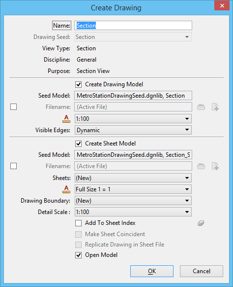
| Setting | Description |
|---|---|
| Name | Shows the name of the saved view that will be created. |
| Drawing Seed | Defines the drawing seed template from which the detailing symbol style will be used for the callout. |
| View Type | Displays the saved view type. The saved view type displayed depends on the saved view settings in the seed file selected in the Drawing Seed drop-down list. |
| Discipline | Displays the discipline of the drawing. It can be modified from the saved view properties in the Properties dialog. |
| Purpose | Displays the purpose of the saved view. It can be modified from the saved view properties in the Properties dialog. |
| Create Drawing Model | If on, creates a drawing model and attaches the saved view coincident at full scale. |
| Seed Model | Displays the seed model from which the drawing model will be created. This seed model is derived from the template selected in the Drawing Seed drop-down list. |
| Filename | If on, you can select the file in which the drawing model will be created. By default, the drawing model is created in the active file. You can create a new file that will contain the new drawing model by clicking Create New Drawing File icon. You can also create the drawing model in another file by click Browse Drawing File icon. |
| Annotation Scale | Sets the scale factor for text and dimensioning in the drawing model. The annotation scale of the drawing model is used as the detail scale when it is attached to a sheet. |
| Visible Edges | Sets the visible edges display option. Options are:
This option is available only when a 3D model is attached directly to a 2D model. In case you are attaching a 3D model directly to a sheet model, this option is displayed under the Create Sheet Model section. You can change the default selection of this drop-down list by defining the MS_REF_VISEDGE_ATTACH_STATE configuration variable. |
| Create Sheet Model | If on, creates a sheet model. If the Create Drawing Model check box is on, the drawing model is attached into the new sheet model. |
| Seed Model | If on, you can select the seed model from which the sheet model will be created. This seed model is derived from the template selected in the Drawing Seed drop-down list, except for the case when you place a named boundary using a drawing boundary with the Create Drawing check box turned on. In this case, the sheet-seed model is the one that contains the drawing boundary. This is to make sure that the drawing fits exactly in the selected drawing boundary. |
| Filename | If on, you can select the file in which the sheet model will be created. By default, the sheet model is created in the active file. You can create a new file that will contain the new sheet model by clicking Create New Sheet File icon. You can also create the sheet model in another file by click Browse Sheet File icon. |
| Sheets | Sets the sheet model in which you want to place the drawing. You can also select New to create a new sheet model. |
| Annotation Scale | Sets the scale factor for text and dimensioning in the sheet model. |
| Drawing Boundary | Sets the drawing boundary in the sheet model where
the drawing will be placed. This option lists the following:
|
| Detail Scale | Sets the detail scale of the drawing attachment in
the sheet model. In addition to standard scales,
Promis.e
calculates following
recommended scales and displays them in this drop-down list:
|
| Add to Sheet Index | Adds the sheet model to the sheet index. |
| Select a folder from Sheet Index | Opens the Sheet Index Folder Picker from which you can select the folder in which the sheet model should be added. |
| Make Sheet Coincident | (Available only if the sheet model does not contain a drawing boundary) If on, the reference in the sheet model is made coincident with the design model. For this, if required, the sheet boundary is moved and rotated to fit around the reference. If off, the reference is moved and rotated so that it is attached at the center of sheet boundary. |
| Replicate Drawing in Sheet File | (Available only when the sheet model is set to be
created in a different file from the current DGN file and that file does not
contain a drawing model) If on, creates a referenced copy of the drawing model
in the file that contains the sheet model. If the file containing the sheet
model is new, the new drawing model is set as the Default model.
This option is particularly useful when you want to
export to DWG. In order to accommodate the 1:1 relationship between model space
and paper space (drawing layout) in a DWG file, this option automates the
addition of a drawing model reference to the sheet model. When you export to
DWG, the new drawing model represents the model space and the sheet model
represents the paper space and is the direct reference of the drawing model
within the sheet.
|
| Open Model | This check box is active when you turn on either the
Create Drawing check box or the Create Sheet check box or both of these check
boxes. If this check box is on, then depending on the setting of Create Drawing
and Create Sheet check box, following operations take place:
|