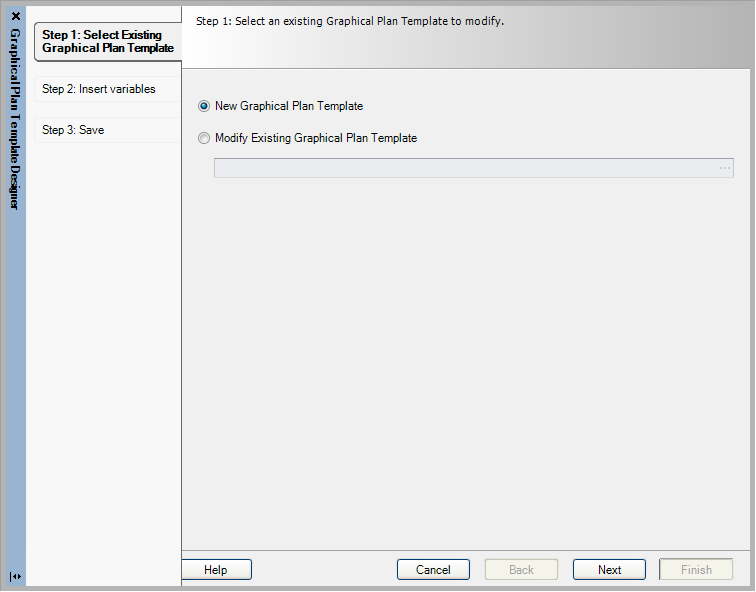
| Select a page format
|
Select a page format to view while designing the
template. Use the Browse button to select from the available formats. This
format appears as a visual reference only and is not saved as part of the
template (in other words, when you generate the graphical plan you can choose a
different page format, if you wish).
|
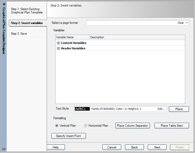
| Variables
|
Provides a list of terminal plan variables that
will act as place holders for information when placed in the template drawing.
The variables are grouped into two categories:
-
Content Variables - For the body of
the terminal plan.
-
Header Variables - Used for column
headings and similar purposes.
Select the + icon to open either of these
categories and display the variables inside. Select the desired variable,
select the
Place button, and then click at the
desired position in the drawing.
|
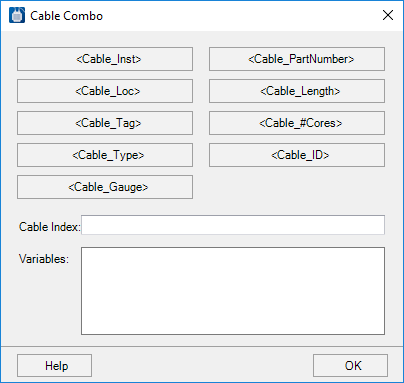
| <Cable Combo>
|
In the
Header variables list, there is a
variable called
<CableCombo>. This variable
allows you to create header entries that identify cables that are connected to
the terminals. When you place this variable, the
Cable Combo dialog will appear:
This dialog provides buttons for a variety of
cable-related variables. When you select a button, that variable is added to
the expression in the
Variables field. This is the information
that will be displayed in the graphical plan header. Make a numeric entry in
the
Cable Index field (1, 2, 3, etc.) to
distinguish between the different cables that you place in the plan. When you
are ready to place the expression in the plan, select the
OK button and then select a position for
the text.
|
| Text Style
|
Displays the text style that will be used for the
variables. If you want to change the text style, use the
Edit button to display the
Edit Text Format dialog.
|
| Formatting
|
In the Formatting area of the dialog, you can make
a number of settings:
-
Vertical Plan - Select this radio
button if you wish terminal information to be displayed from top to bottom on
the page.
-
Horizontal Plan - Select this radio button if you wish information to
appear from left to right on the page.
-
Place Column Separator - Defines a column dividing line in the template.
Click on a point where the line should begin. This will be marked in the
template with an X. When the graphical plan is generated, the line will be
extended from this point to match the amount of information in the column.
Note: The number
of column separators on the graphical plan template should equal the number of
content variables plus one additional. The table start icon is not considered a
column separator.
-
Place Table Start - Defines a starting
point for the data rows of the graphical plan. Select the button and click on
the desired point.
|
| Specify Insertion Point
|
Defines the insertion point for the graphical plan
template on the page. Select the button and click on the desired point in the
drawing. Generally, you should select a point at the upper left corner of the
template. When you generate graphical plans automatically, the insertion point
will be placed on the page at the upper left as defined by the top and left
page margins.
|
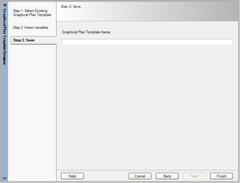
 The
Graphical Plan Template Designer lets the user
create custom templates for graphical plans.
The
Graphical Plan Template Designer lets the user
create custom templates for graphical plans.