Display Formats
The Display Formats mode is accessed from the Project Options dialog and allows the user to set the format of device IDs, cross references and part numbers.

| Setting | Description |
|---|---|
| Adjust device ID when symbol(s) is moved | Enable when you want a symbol's ID to be updated when the symbol is moved. For example, when the ID format includes the line number and the symbol is moved to a different line. |
| Make Device ID Uniqueness Case Sensitive |
Enable this option have the case of letters in an ID to make a difference. For example, if this box is selected then LS2 and Ls2 will be considered two different IDs. If the check-box is not selected, then the following options are available for making the case of IDs consistent: |
| Nested Device ID |
|
| Device ID Format |
For each format type, the dialog shows the name of
the format that defines what the ID is currently based on ( page and line
number, sequential number, etc.).
To change the elements that make up an ID, select the Edit button inside the field for a given format type to access the Device ID Format dialog. Note: The Schematic
(PLC Wired Device ID) and Schematic (PLC Wired Terminal ID) device ID formats
will only be applied when the Replace Device ID function is used. The PLC Wired
Device ID will assign the PLC address to the first non-terminal device
connected to the PLC. The PLC Wired Terminal ID will assign the PLC address to
the first terminal connected to the PLC.
Note: When creating
a PLC symbol, the connection points order needs to include all of the addressed
connections in order. Non-addressed connections need to appear after the
addressed points. This also applies to PLC families (children with addresses
should appear before children without addresses).
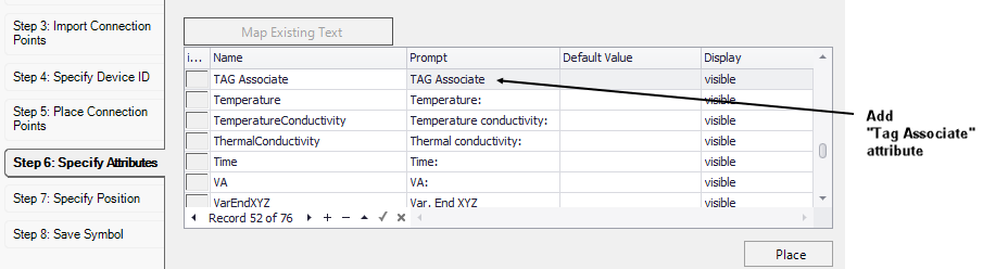
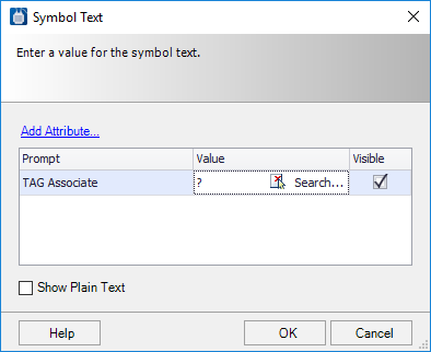
Some users require that a symbol display not only
its own device tag but also the tag of some other device that it is connected
to or associated with. This is done when you create a symbol using the Symbol
Creation Wizard.
|
| Device Cross Reference | A device cross reference is a cross reference that links two or more symbols in the schematic drawings. Examples would be the cross references between the coil and contacts of a relay or between a PLC parent and its child symbols. Select the Device Cross Reference line and press Edit to display the Device Cross Referencing dialog. |
| Wire Link Cross Reference | Click in the field and press Edit to display the Wire Link Cross Reference Format dialog. |