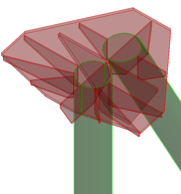
Vertical A Frame Cap
 Used to parametrically create
vertical A frame cap connections, mostly commonly used in electrical
substations.
Used to parametrically create
vertical A frame cap connections, mostly commonly used in electrical
substations.
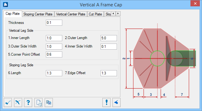
Cap Plate tab
Used to specify geometry for the cap plate.
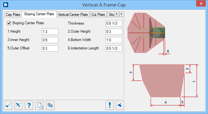
Sloping Center Plate tab
Used to specify geometry for the sloping center plate.
| Setting | Description |
|---|---|
| Sloping Center Plate | When on, the sloping center plate is included in the connection. |
| Thickness | Sets the thickness of the sloping center plate. |
| Height | Sets the overall height of the plate. Denoted with 1 in the diagram. |
| Outer / Inner Height | Sets the height above the cut corners on either side of the plate, respectively. Denoted with 2 and 3 in the diagram. |
| Bottom Width | Sets the width of the plate at the bottom. Denoted with 4 in the diagram. |
| Outer Offset | Sets the offset from the plate outer edge at the bottom of the plate. Denoted with 5 in the diagram. |
| Indentation Length | Sets the offset between the sloping center plate and the top cap edge. Denoted with 6 in the diagram. |
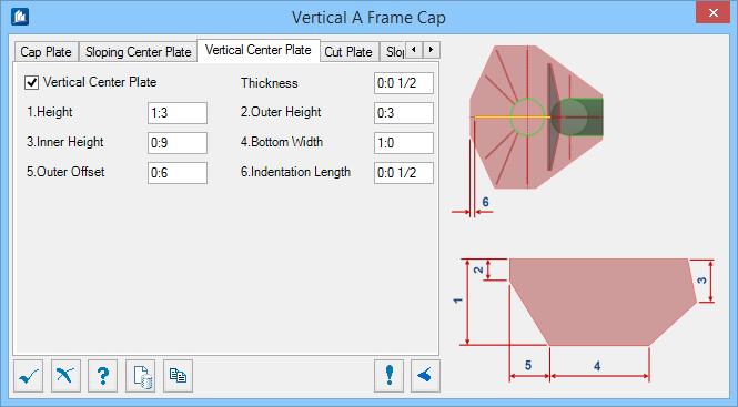
Vertical Center Plate tab
Used to specify geometry for the vertical center plate.
| Setting | Description |
|---|---|
| Vertical Center Plate | When on, the vertical center plate is included in the connection. |
| Thickness | Sets the thickness of the vertical center plate. |
| Height | Sets the overall height of the plate. Denoted with 1 in the diagram. |
| Outer / Inner Height | Sets the height above the cut corners on either side of the plate, respectively. Denoted with 2 and 3 in the diagram. |
| Bottom Width | Sets the width of the plate at the bottom. Denoted with 4 in the diagram. |
| Outer Offset | Sets the offset from the plate outer edge at the bottom of the plate. Denoted with 5 in the diagram. |
| Indentation Length | Sets the offset between the vertical center plate and the top cap edge. Denoted with 6 in the diagram. |
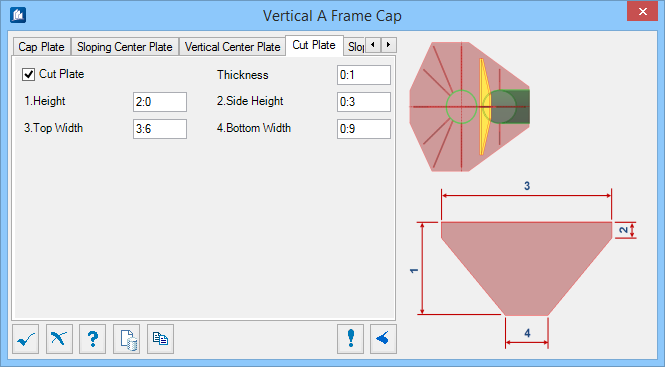
Cut Plate tab
Used to specify geometry for the cap plate.
| Setting | Description |
|---|---|
| Cut Plate | When on, this plate is included in the connection. |
| Thickness | Sets the thickness of the cut plate. |
| Height | Sets the overall height of the plate. Denoted with 1 in the diagram. |
| Side Height | Sets the height above the cut corners on both sides of the plate, respectively. Denoted with 2 in the diagram. |
| Top / Bottom Width | Sets the width of the plate at the top and bottom respectively. Denoted with 3 and 4 in the diagram. |
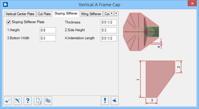
Sloping Stiffener tab
Used to specify geometry for the sloping stiffeners on either side of the sloping leg member.
| Setting | Description |
|---|---|
| Sloping Stiffener Plate | When on, the sloping stiffener plate is included in the connection. |
| Thickness | Sets the thickness of the sloping stiffener plate. |
| Height | Sets the overall height of the plate. Denoted with 1 in the diagram. |
| Side Height | Sets the height above the cut corners on both sides of the plate, respectively. Denoted with 2 in the diagram. |
| Bottom Width | Sets the width of the plate at the bottom. Denoted with 3 in the diagram. |
| Indentation Length | Sets the offset between the sloping stiffener plate and the top cap edge. Denoted with 4 in the diagram. |
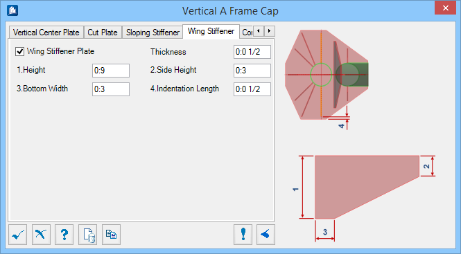
Wing Stiffener tab
Used to specify geometry for the stiffener plates on either side of the vertical leg member.
| Setting | Description |
|---|---|
| Wing Stiffener Plate | When on, the wing stiffener plate is included in the connection. |
| Thickness | Sets the thickness of the wing stiffener plate. |
| Height | Sets the overall height of the plate. Denoted with 1 in the diagram. |
| Side Height | Sets the height above the cut corners on both sides of the plate, respectively. Denoted with 2 in the diagram. |
| Bottom Width | Sets the width of the plate at the bottom. Denoted with 3 in the diagram. |
| Indentation Length | Sets the offset between the sloping stiffener plate and the top cap edge. Denoted with 4 in the diagram. |
Corner Stiffener tab
Used to specify geometry for the stiffener plates adjacent to the wing stiffeners, on either side of the vertical leg member.

| Setting | Description |
|---|---|
| Corner Stiffener Plate | When on, the corner stiffener plate is included in the connection. |
| Thickness | Sets the thickness of the corner stiffener plate. |
| Height | Sets the overall height of the plate. Denoted with 1 in the diagram. |
| Side Height | Sets the height above the cut corners on the side of the plate. Denoted with 2 in the diagram. |
| Bottom Width | Sets the width of the plate at the bottom. Denoted with 3 in the diagram. |
| Indentation Length | Sets the offset between the corner stiffener plate and the top cap corner. Denoted with 4 in the diagram. |
| Offset | Sets the length from the working point/center of the sloping leg to the end of the cap plate. Denoted with 5 in the diagram. |
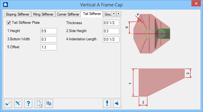
Tail Stiffener tab
Used to specify geometry for the tail stiffeners, on either side of the vertical center plate.
| Setting | Description |
|---|---|
| Tail Stiffener Plate | When on, the tail stiffener plate is included in the connection. |
| Thickness | Sets the thickness of the tail stiffener plate. |
| Height | Sets the overall height of the plate. Denoted with 1 in the diagram. |
| Side Height | Sets the height above the cut corners on the side of the plate. Denoted with 2 in the diagram. |
| Bottom Width | Sets the width of the plate at the bottom. Denoted with 3 in the diagram. |
| Indentation Length | Sets the offset between the corner stiffener plate and the top cap edge. Denoted with 4 in the diagram. |
| Offset | Sets the length from the working point/center of the sloping leg to the end of the cap plate. Denoted with 5 in the diagram. |
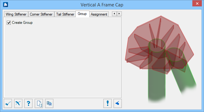
Group tab
Used to create a new ProStructures group with the Substation Gallery objects.
| Setting | Description |
|---|---|
| Create Group | Select this option to select additional shapes. Separate Substation Gallery objects are created. |
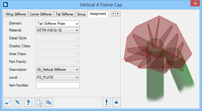
Assignment tab
Used to assign elements in the connection to a material, display class, area class, part family, level, etc.
Dialog Controls
| Setting | Description |
|---|---|
 OK OK
|
Closes the dialog and save your changes. |
 Cancel Cancel
|
Closes the dialog without saving changes. |
 Help Help
|
Opens online help. |
 Template Template
|
Saves and retrieve (Using Templates) settings to be used on other projects. |
 Clone Clone
|
Shifts focus to the geometry, allowing cloning the current structural object (stair, frame, truss, etc.) properties to match one or more objects selected in the view. |
 Apply Apply
|
Updates the current model object with any changes made in the dialog settings. |
  Show /Hide
Preview Show /Hide
Preview
|
Opens or closes, respectively, a flyout panel to display an illustration based on the tool. |