Trestle Cap
 Used to parametrically generate a
cap plate for a trestle frame, commonly used in electrical substations.
Used to parametrically generate a
cap plate for a trestle frame, commonly used in electrical substations.
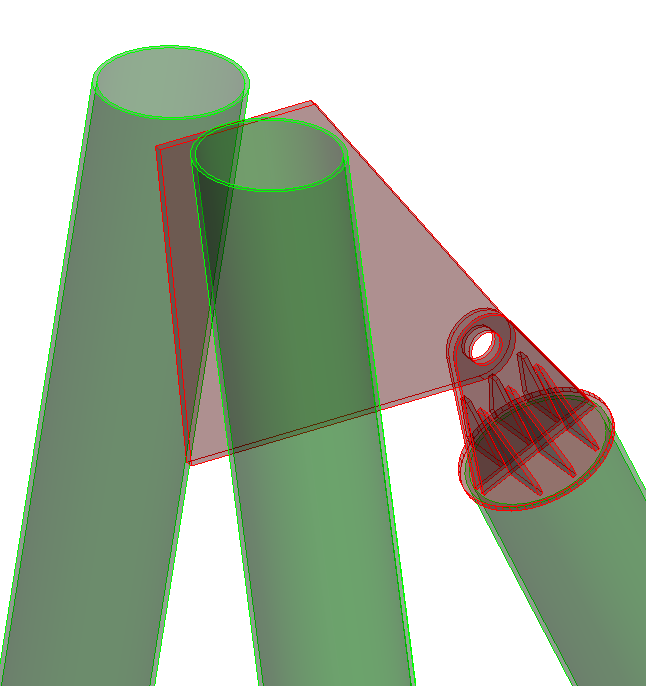
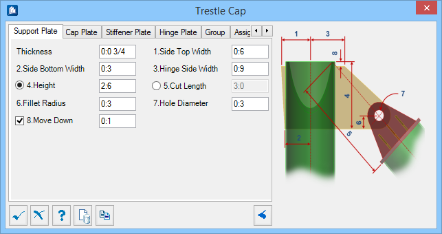
Support Plate tab
Used to specify the geometry of the hinge connection plate on the top of the trestle (between the two main legs).
| Setting | Description |
|---|---|
| Thickness | Sets the thickness of the support plate. |
| Side Top Width | Sets the width measured from the center of the main legs to the outer edge of the plate at the top. Denoted with 1 in the diagram. |
| Side Bottom Width | Sets the width measured from the center of the main legs to the outer edge of the plate at the bottom. Denoted with 2 in the diagram. |
| Hinge Side Width | Sets the width measured from the center of the main legs to the hinged edge of the plate at the top. Denoted with 3 in the diagram. |
| Height | When on, sets the overall height of the plate. When off, the overall height is calculated by setting the Cut Length parameter. Denoted with 4 in the diagram. |
| Cut Length | When on, sets the overall length of the plate (measured from the trestle main legs to the cap plate). When off, the overall length (Cut Length) is calculated by setting the Height parameter. Denoted with 5 in the diagram. |
| Fillet Radius | Sets the radius of the rounded plate corner. Denoted with 6 in the diagram. |
| Hole Diameter | Sets the radius of the plate hole. Denoted with 7 in the diagram. |
| Move Down | When on, you can enter an offset distance from the top of the trestle legs to the top of the support plate. When off, the offset is zero. Denoted with 8 in the diagram. |
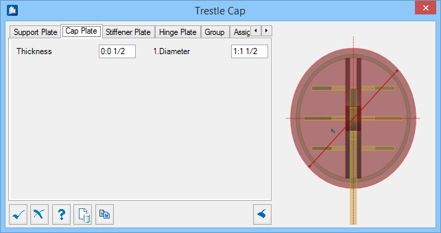
Cap Plate tab
Used to specify the geometry of the cap plate.
| Setting | Description |
|---|---|
| Thickness | Sets the thickness of the cap plate. |
| Diameter | Sets the diameter of the cap plate. Denoted with 1 in the diagram. |
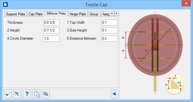
Stiffener Plate tab
Used to specify the geometry of stiffeners placed on either side of the hinge plates.
| Setting | Description |
|---|---|
| Thickness | Sets the thickness of the trestle stiffener plate. |
| Top Width | Sets the width of the plate at the top. Denoted with 1 in the diagram. |
| Height | Sets the overall height of the plate. Denoted with 2 in the diagram. |
| Side Height | Sets the height of the plate on the right. Denoted with 3 in the diagram. |
| Circle Diameter | Sets the diameter of the circular pattern made by the stiffener plates which also determines the widths at the bottoms of the plates. Denoted by 4 in the diagram. |
| Distance Between | Sets the distance between the plates. Denoted by 5 in the diagram. |
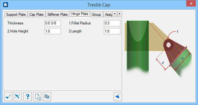
Hinge Plate tab
Used to specify the geometry of hinge plates.
| Setting | Description |
|---|---|
| Thickness | Sets the thickness of the trestle hinge plate. |
| Fillet Radius | Sets the radius of the rounded plate corner. Denoted with 1 in the diagram. |
| Hole Height | Sets the distance between the hole and the trestle cap plate. Denoted with 2 in the diagram. |
| Length | Sets the length of the plate where it is attached to the trestle cap. Denoted with 3 in the diagram. |
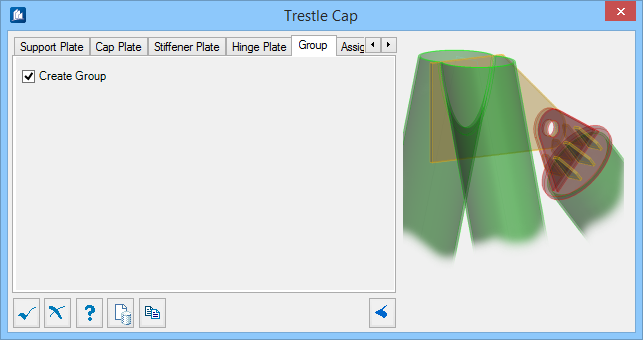
Group tab
Used to create a new ProStructures group with the Substation Gallery objects.
| Setting | Description |
|---|---|
| Create Group | Select this option to select additional shapes. Separate Substation Gallery objects are created. |
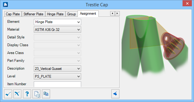
Assignment tab
Used to assign elements in the connection to a material, display class, area class, part family, level, etc.
Dialog Controls
| Setting | Description |
|---|---|
 OK OK
|
Closes the dialog and save your changes. |
 Cancel Cancel
|
Closes the dialog without saving changes. |
 Help Help
|
Opens online help. |
 Template Template
|
Saves and retrieve (Using Templates) settings to be used on other projects. |
 Clone Clone
|
Shifts focus to the geometry, allowing cloning the current structural object (stair, frame, truss, etc.) properties to match one or more objects selected in the view. |
 Apply Apply
|
Updates the current model object with any changes made in the dialog settings. |
  Show /Hide
Preview Show /Hide
Preview
|
Opens or closes, respectively, a flyout panel to display an illustration based on the tool. |