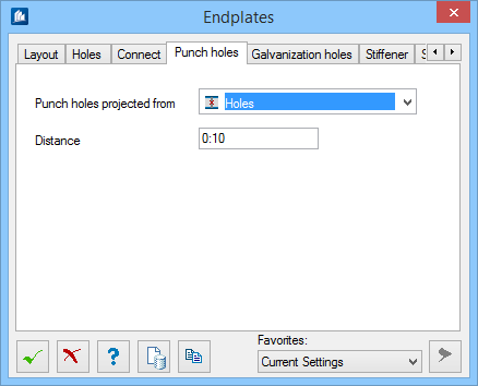
| Punch holes projected from
|
- None – No punch
holes are added.
- Web (For
Normal layouts) – Punch holes are added on the
endplate where the web projects, at either side of the mid-depth of the web.
- Shape
Vertices (For
Normal layouts) – Punch holes are added on the
endplate at the projected corners of the connecting shape.
- Holes (For
Flange layouts) – Punch holes are added at a
projection to the nearest flange of the connected beam. If symmetric, the left
flange is used.
- Endplate
Edges (For
Flange layouts) – Punch holes are added a
project to the outer edges of the nearest flange.
Note: When a doubler
plate is present, the plate dimensions of the first endplate in the connection
(i.e., the endplate closes to the connecting beam) are used.
|
| Distance
|
(Enabled for
Flange layouts, where
Holes or
Endplate Edges is selected as the
Punch holes projected from drop-down list) –
Sets the distance from the edge of the flange to the punch hole.
|