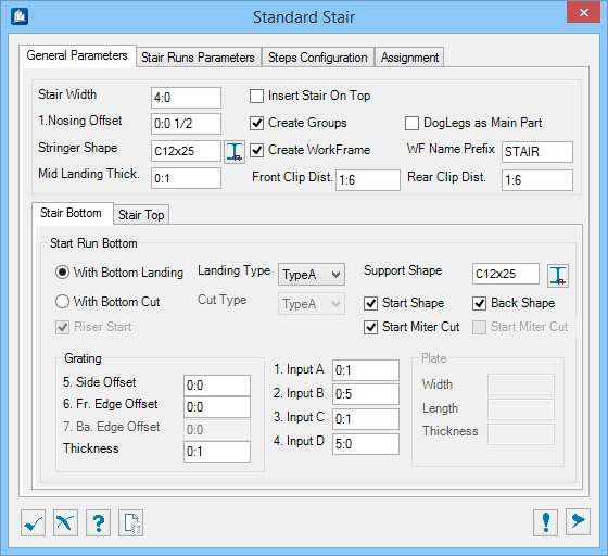
| Stair Run Bottom
|
Activates one of the two options available to use at the bottom
of the stair run:
- With
Bottom Landing – The stair has a landing at the bottom using the
indicated landing parameters.
- With
Bottom Cut – The stringers are cut as indicated a the bottom (no
landing).
Refer to the dynamic illustration for details on the selected
type using the Show Preview button.
|
| With Bottom Landing
|
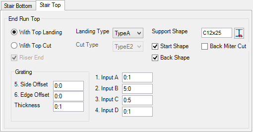
Activates the landing type and shape settings
- Landing
Type – Sets one of the predefined landing configurations from the
drop-down list.
- Type
A – Activates support member's shape size and settings.
- Support
Shape – Displays the shape size for the currently selected support
member.
-
 (Select Shape tool) – opens
Shape Selection dialog where desired shape
size is selected. (Select Shape tool) – opens
Shape Selection dialog where desired shape
size is selected.
- Start
Shape – When checked, use sa start support shape at the front of
the bottom landing.
- Back
Shape
– When checked, uses a back support shape at the
start of the stair bottom (i.e., beneath the upper end of the stringers).
Activated for Landing
Type A only.
- Start
Miter Cut
– When checked, uses a miter cut between the
landing stringers and the start support shape.
When unchecked, the start support shape is cut at the face
of the landing stringers (front of the landing).
- Leg Miter
Cut
– When checked, uses a miter cut between the stair
stringer and the landing stringer.
When unchecked, the landing stringers are cut at the face of
the stair stringer vertical end.
Activated for Landing
Type B only
|
| With Bottom Cut
|
- Activates bottom cut
settings:
- Cut
Type – Sets one of the predefined stringer cut configurations from
the drop-down list. The necessary inputs for the selected type are active
fields on this tab (other inputs are made inactive).
- Riser
Start – When checked, starts the stair run at the height of a
riser. When unchecked, the stair run starts at the elevation of the selected
insert point.
|
| Grating
|
- Side
Offset – The distance the side edges (i.e., over the landing
stringers) should extend over the landing stringers. Use a negative offset to
create a gap between the stringers and the side edges of the grating.
- Fr Edge
Offset
– The distance the back edge of the grating (i.e.,
over the back support) should extend over the back support (if
Start Shape is set) or the end of the
landing stringers.
- Ba. Edge
Offset – (for Landing Type B only) The distance the back edge of
the grating (i.e., over the back support) should extend over the back support
(if
Back Shape is checked) or the end of the
landing stringers.
- Thickness –
Sets the thickness of the grating used for the lower landing.
|
| Input A, B, C, D
|
Sets the user inputs to the active dimension field.
These dimensions vary based on the selection of landing or cut and the type of
landing or cut selected. (Refer to the dynamic illustration preview pan to
relate the input dimensions).
|
| Plate
|
Activated for bottom cut
Type C only. Sets the dimension in
respective fields. The plate dimensions are used to define the base plate shape
for the stair stringer.
|