To define a cross section
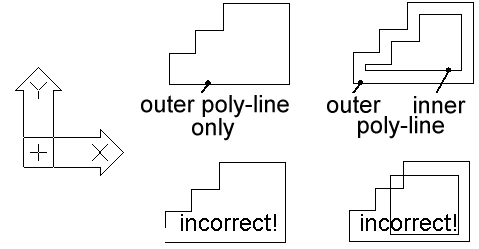
Defining the closed and the not crossing contour of the cross-section normally creates a special shape. Depending on the setting, this can be done using poly-lines or individual lines and arc segments.
Alternatively, you can define special shapes of regular wall thickness (e.g. cold rolling shapes) by means of an open poly-line and by specifying the thickness. See ‘Settings’.
After selection, choose your outer contour and the possibly existing inner contours. You can utilise any number of inner contours that must not cross the outer contour and must not have any intersection points between each other.
Now, the program automatically calculates the possible standard insertion points of this shape (center line, envelope). Finally, you can still define a center line which can be used alternatively and further insertion points.
After end of the geometrical definitions, now the property dialog for specifying the parts list data will be displayed.
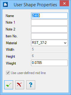
Enter the name of the parts list, notes, material, etc.
Starting from the cross-section drawing and the entered material data, the program calculates the weight in kg/m and displays it in the entry field Weight. You can determine which shape data will be applied to the standard parts list. It is also possible to change the calculated weight.
When you have defined a user-defined center, you also specify here whether it is used to determine the center line or whether the calculated center line has to be used.
Then, the special shape is saved and can be used by you in the 3D-model.
As you can see, the defined resolution is displayed. You could repeat this procedure with different resolutions or modify any existing resolution afterwards as described above.