| Dimension
|
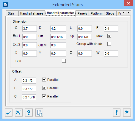
- G – Sets the
distance from the topmost point on the handrail/top rail to the bottommost
point of the walkway. This is the overall height from the top of the platform
or step.
- D – Sets the
distance from the center of one post to the center of the next post. This is
the maximum distance from post to post at insertion points. The tool equally
spaces the posts as close to this value as possible.
- L – Sets the
distance from the center of the closure shape to the end of the walkway. This
option controls the distance of the handrail posts from the end of the platform
on intermediate platforms. It does not affect the topmost platform handrail
(S2, in Stair tab).
- F – Sets the
distance from the center of one filler rod to the center of the next filler
rod. This option is where you would enter your preferred center to center
spacing of the filling rods (the
V Shape in Handrail shapes tab). This
may change if
Max is checked.
- Ext
1 – Sets the spacing placed between the handrail and top of the
post. This is the Superior extension of the post. The space will be filled in
with the shape that is defined by Shape
E in Handrail shapes tab.
- Off – Sets the
Offset extension plate. When a space using the
Ext 1 is used a cap plate will be placed
at the top of the post. This value will trim back the cap plate along the edges
by the value specified so that it is not flush with the outer edges of the
post.
- Sp – When
a space using
Ext 1 is used a cap plate will be placed
at the top of the post. This value will determine the thickness of the cap
plate that is placed.
- Max – When
checked, creates maximum distance bars. The filling rods defined in
V Shape in Handrail shapes tab and
spaced in
F will be equally spaced all the way
across, as close to the value set in
F as possible without going over. When
unchecked, all the filling rods will be spaced at the exact distance specified
in
F and any remaining distance will be
divided equally at either end before the posts.
- Ext
2 – Determine how far the bottom of the posts can be extended
downwards. This is the Inferior extension of the post. Applicable when the Side
offset post
Off-M value is great enough that it will
push the handrail out so that it does not land on the stringer.
- Off
M – Sets the Side offset posts. This will push the entire handrail
outwards by the value specified. If the value is large enough that the posts no
longer rest on the stringer then the value used in
Ext 2 will extend the posts downwards by
that value.
- Group
with cheek – When checked, creates a single group with the handrail
and the cheek shapes (Stringers).
- X – When
creating a manual angle cut at the top of the posts, this will determine the
height of the angular cut from the top of the post down. When combined with
Y or
Z creates and angular cut along the
edges.
- Y – When
creating a manual angle cut at the top of the posts, this will determine the
distance from the inside edge towards the center. When combined with
X this creates and angular cut along the
inside edge.
- Z – When
creating a manual angle cut at the top of the posts, this will determine the
distance from the outside edge towards the center. When combined with
X this creates and angular cut along the
outside edge.
- W – Sets the
offset of the handrail from the step, by the amount entered in this field. A
positive value creates the offset outside and a negative value create the
offset inside.
- Center
posts on step
– When checked, centers the posts on the steps,
only for the oblique sector. All the posts placed above steps will be adjusted
so that they remain equally spaced but also centered over a step.
Note: This may move the starting post up along the stringer.
|
| Offset
|
- A – Sets the
distance between the bottom of the handrail/top rail and the top of the inner
rail. This is the distance from the bottom of the handrail to the center of the
top rail which supports the filling rods. Used for defining the height of the
top rail.
- B – Sets the
distance from the bottom of the bottom rail to the top of the walkway. This is
the distance from the top of the stringer to the center of the bottom rail
which supports the filling rods. Used for defining the height of the bottom
rail.
- C – Sets the
distance from the centerline of the kick plate to the top of the walkway. This
is the distance from the top of the stringer to the center of the kick plate.
Used for defining the height of the kick plate.
- Parallel
– When checked, measures the offsets at parallel
distances. The distance between members is determined at the same oblique angle
as the members are travelling in. When unchecked, the distance between members
is determined vertically regardless of the angle. Each parallel option relates
to the offset
A,
B or
C beside it.
|