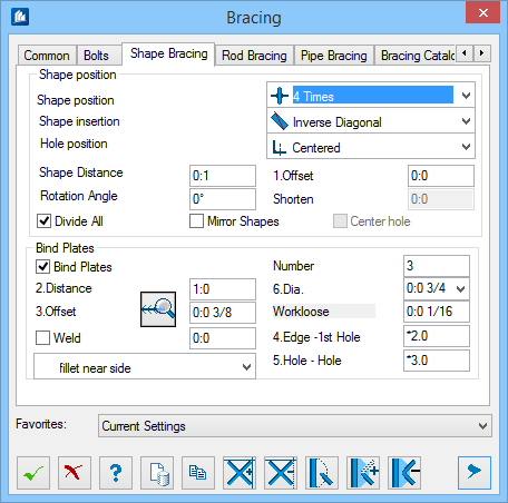
| Shape Position settings
|
- Shape
Position –Sets select the position of the shapes in relation to the
gusset plates.
- Front- the shapes are located in front
of the gusset plate.
- Back - The shapes are located behind
the gusset plate.
- Cross
- One shape is located in front of the gusset plate and one behind.
- Centered - The shapes are located in
the bracing plane.
- Double – One shape each is located in
front of and behind the gusset plate (total of 4 shapes for cross stay).
- Replaced – One shape each is located
in front of and behind the gusset plate with one being offset to the left and
one to the right (total of 4 shapes for cross stay).
- 4-Times– One shape is located on each
side (front, rear, left, right), which makes a total of 8 shapes for cross
stay.
- Shape
Insertion – Sets the insertion position of the shapes.
- Centered - The shapes are inserted
along the shape axis..
- COG
Line - The shapes are inserted along the COG (Center of Gravity) line.
- Pitch Line – The shapes are inserted
along the pitch line.
- Diagonal – The shapes are inserted
along their corner points Upper Edge Left up to Lower Edge Right..
- Inverse Diagonal – The shapes are
inserted along their corner points from Lower Edge Left up to Upper Edge
Right.
- Hole
Position – Sets the hole positions in the shape.
- Centred - The holes are drilled on the
shape axis.
- COG
Line - The drill holes are drilled on COG line.
- Pitch Line – The holes are drilled on
the shape pitch line.
- Shape
distance – Sets the distance of the shapes for offset or 4-Times
bracings.
- Rotation
Angle – Used to specify a rotation of the shapes.
- Offset –
Specify a projection of the central gusset plate extending past the shape edges
of the bracing bars. Positive values increase the size of the plate whereas
negative values decrease it.
- Shorten – Here
you can specify a value to be used to shorten the shapes after the bracing has
been generated.
- Divide
All – If this field is checked, all shapes of a cross stay are
separated at the center gusset plate.
- Mirror
Shapes – If this field is checked, the shapes are mirrored and then
inserted.
- Center
hole – At a cross stay and selected shape position 'Crossed', a
common hole is drilled into the shapes that are crossing each other.
|
| Bind Plates settings
|
Enabled for guess plate shape position set to
4 times. Used to add binding plate between the
bracing rods.
- Bind
Plates – When checked, enables the following settings used for a
further description of the batten plates. Used when opposing shapes have batten
plates as stiffeners.
- Distance – Sets
the distance of the batten plates; the program divides the distances regularly
according to this specification and the values are rounded up or down
correspondingly.
- Offset – Sets
the distance of batten plates from the shape edges. Positive values decrease
the size of the plate whereas negative values increase it, i.e. the plate has a
projection.
- Weld – When
checked, the batten plates are not connected by bolts but by a weld. Welds the
binding plate instead of bracing rods.
- Weld input field
– Sets the weld thickness in the input field, if it differs from the default
settings of the weld style.
- Weld style –
Lists the weld styles in the selection list.
 (Edit Style) – Opens Weld Styles
dialog used to process the weld style or to create a new style. (Edit Style) – Opens Weld Styles
dialog used to process the weld style or to create a new style.
- Number – Sets
the number of bolts which are used to connect each batten plate with the
shapes.
- Dia. – Sets the
diameter of bolting to connect binding plates.
- Workloose –
Sets the hole work loose of bolting. This is the allowable play between the
hole diameter and bolt diameter.
- Edge-1st
hole – Sets the distance from the end of the batten plate to the
first hole center in the direction of the bar.
- Hole-Hole – The
space between the drilled holes in the direction of the bar
|