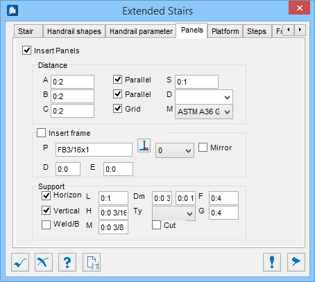
| Insert frame
|
When checked, adds a frame around the panel between
the posts of the handrail. The frame is placed around the panel as per settings
selected in this section. The values
A,
B and
C will then apply to the outside of the
frame rather than the outside of the panel.
- P – Displays
the currently specified shape for the frame of the panel.
 (Select Shape tool) – Opens the
Shape Selection dialog, used to select a catalog shape from a list of standard
shapes and sizes for the frame surrounding the panel. (Select Shape tool) – Opens the
Shape Selection dialog, used to select a catalog shape from a list of standard
shapes and sizes for the frame surrounding the panel.
- Rotation
(Drop-down) – Allows selecting the rotation of the selected frame shape. Select
a rotation angle (at 90° increments) from the drop-down list. The outer edge of
the frame remains in the same location.
- Mirror – When
checked, mirrors the selected frame shape orientation along its longitudinal
axis. Useful in some cases where the shapes needs to be mirrored in order to
achieve the proper placement.
- D – Sets the
distance from the top of the panel frame to the top of the panel. This option
places a 'parallel' offset between the panel and the inside of the frame at the
top and bottom. The panel is resized inwards, the frame remains the same size.
- E – Sets the
horizontal distance from the outer edge of the panel frame to the edge of the
panel. This option places a 'parallel' offset between the panel and the inside
of the frame at the sides. The panel is resized inwards, the frame remains the
same size.
|
| Support
|
- Horizontal –
When checked, adds horizontal supports to the panel frame with the settings
selected in this section. Panels are attached by supports on both sides.
- Vertical – When
checked, adds vertical supports to the panel frame with the settings selected
in this section. Panels are attached by supports on both top and bottom sides.
- Weld/Bolt –
When checked, adds bolted supports. The connection between the frame and the
supporting members will be made using two plates bolted together. When
unchecked, a single member is used.
- L – Sets the
width of the panel supports. This value controls the width of the plate(s) used
to attach the frame to the supporting members.
- H – Sets the
thickness of the panel supports. This value controls the thickness of the
plate(s) used to attach the frame to the supporting members.
- M – Sets the
offset measured from the insides of the bases of the panel supports to the ends
of the connecting panel supports. If bolted this is the distance between the
edge of the frame or supporting member and the edge of the plate. One plate
will be attached to the frame and offset from the supporting member while the
other plate is attached to the supporting member and offset from the frame. The
bolt hole in each plate will line up for bolting.
- Dm – Sets the
diameter of the hole in the panel supports, and the diameter of the play hole.
- Dm(1) – The
diameter of the bolt hole.
- Dm(2) – The
tolerance of the bolt hole.
Note: Not
applicable when the
Weld/Bolt is set for support parts.
- Ty – Sets the
bolt type from the drop-down list. To add or modify this list. refer to the
Bolt Styles topic in this help.
- Cut – When
checked, cuts holes in the panel support plates. The support plates are cut so
that they are flush with the supporting members.
- F – Sets the
horizontal distance from the center of a vertical support to the edge of the
panel. This is the distance from the bottom and top edge of the panel or frame,
along the sides, to the center of the attachment plates.
- G – Sets the
vertical distance from the center of a horizontal support to the edge of the
panel. This is the distance from the bottom and top edge of the panel or frame,
along the sides, to the center of the attachment plates. Adjusting these values
will adjust where the plates are placed.
|