| Layout
|
-
12 Numerical / AB Alphabetical
– Choose the axis name type that describes the
numbering format for axes. The designations may either be numerical (123) or
alphanumerical (ABC).
-
Text, Circle... – Defines the axis
description label format. Here you specify the depiction of the text. The text
can either be displayed just as it is or with the selected border. If you have
selected cell depiction, you may use an own text design.
- Connection Line
– A line is drawn from the corresponding edge of the work frame to the text.
|
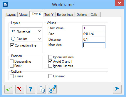
| Values group
|
- Start
Value – Indicates the start of automatic axes names.
- Size – The text
size is specified. At cells it is defined by the attribute size.
- Scale – You can
enter a scale for the cells.
- Distance –
Indicates the distance of the text to the edge of the work frame.
- Main
Axis – When several work frames are involved, you can here enter
the name of the main work frame, if the current frame is rather considered to
be a subordinate frame. It can also be used as prefix.
- Ignore
Last Axis
– When frames are used, the axes names can
overlap. This option suppresses the display of the last axis.
- Avoid O
and I – When alphanumerical axes names are used, you can refrain
from using I and O to avoid any possibility of confusion.
- Suppress
1st Axis
– When frames are used, the axes names can
overlap. This option suppresses the display of the first axis.
|
| Position group
|
- Descending –
Normally, axis labeling is effected in increasing order, e. g. 1, 2, 3, etc.
This option has the opposite effect.
- Back /
Left – The axes can be attached either in front or at the rear, or
on the left or on the right.
|
| Options group
|
- 2
Lines – Main and subordinate axes are displayed in 2 lines.
- Dynamic – The
axes names are always adapted to the corresponding view direction. Thus, a good
readability will be guaranteed at any time.
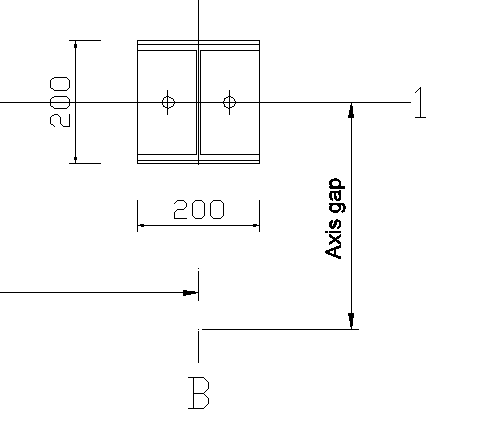
- Axis
Gap – Here, the distance of the actual grid to the connection line
of axis name is indicated.
Note: This entry is
only displayed if you edit the grid in a 2D detail.
|
 Edit Individual Axis Names Edit Individual Axis Names
|
Click on this button to edit the different grid axes
individually.
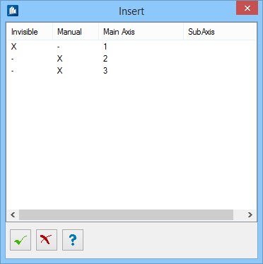
The
Insert dialog is used to enter the name and
the main axis for each single axis. In addition, you can specify whether the
axis name has to be overwritten manually (manual) and whether this axis has to
be displayed (invisible).
Double-clicking in the first two columns switches
the entries (X mark). The entries of the last two columns can be edited by
double-clicking.
|