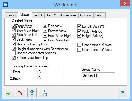
| Created Views
|
- Front
View
– A view on the front view is created.
- Side View
Right – A view on the right side view is created.
- Side View
Left – A view on the left side view is created.
- Back
View – A view on the back side is created.
- Plan View
– A view on the horizontal roof area is created.
- Bottom
View
– An underside view is created.
- Roof View
Right – A view upon the right roof area is created.
- Roof View
Left – A view on the left roof area is created.
- Length
Axis (Y) – A view is created for each created axis into the depth.
- Width
Axis (X) – A view is created for each created axis into the width.
- Height
Axis (Z) – A view is created for each created axis into the height.
- Use Axis
Descriptions – Creates the names of the workframe. You can either
select standardized names such as X_1,X_2 for length and width axes or you can
use the specified axes names.
- Height
dimensions with Coordinates – For the height axes, the heights are
additionally added to the name. When on, creates the names of the elevation
frames using the prefix and the Z-coordinates.
- Update
connected Shapes – Updates the position of shapes which have been
inserted along a line of this workframe.
- Bottom
view from Top – Sets the view direction of the bottom view from the
top instead of from below.
- Segment
Axis – Applicable for
Cylindrical layout. Creates workframes for
segment faces.
- User-defined
X-Axes – A view is created at for the manually added X-axes.
- User-defined
Y-Axes – A view is created at for the manually added Y-axes.
|
| Clipping Plane Distances
|
The views can automatically hide all elements
situated outside a certain distance. Here, you specify these distances for all
views of this work frame, separated in:
- Front –
Specifies the distance from
front clipping plane to workframe.
- Back –
Specifies the distance from
back clipping plane to workframe.
|
| Group Name
|
Since several work frames may be inserted into one
drawing, these have to be equipped with their own code. Determines the name of
group of opinions, which is placed in front all produced work areas. In this
case, it is R1_X2.
|