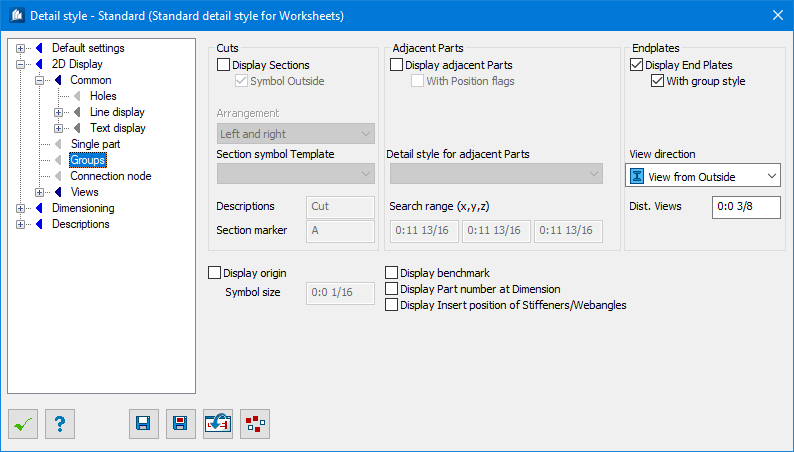
| Display Sections
|
2D-cuts (manual or automatic at e.g. stiffeners)
inserted into the main part are added as additional view to the group.
Here you have to differentiate between 2D-cuts in
the model and 2D-cuts in the details: 2D-cuts inserted in the model only define
whether and how a detail has to be cut at detailing process.
- Only
manual – Only manually added cuts are displayed. Cuts automatically
determined by the program are not depicted.
- Equals
only once – Cuts having an identical display are only depicted
once.
|
| Symbol Outside
|
Cut arrows are displayed outside of the last
dimensioning chains. Otherwise, they are fixed directly at the part even in
front of the dimensioning chains.
|
| Arrangement
|
Sets the position of the partial view —Left and
right, Below stacked, and Below continuous. The cuts are not depicted on the
left and/or on the right of the main view (mostly the front view), but beneath
the last views, one beside the other.
|
| Section Symbol Template
|
Here, you can select a template describing the
display of cut labeling. These templates can be defined within the command
Insert 2D cut.
|
| Descriptions
|
Here, you indicate the cut designation (without the
code letter for cut) that has to be used for labeling the cut views.
|
| Section Marker
|
Here, you enter the cut code letter (or number) that
has to be used to describe the first cut of a group as section index. All other
cuts of this group will be counted accordingly in increasing order.
|
| Display Adjacent Parts
|
The neighboring parts of a group are also depicted.
These are the parts where the group is connected, which however don’t belong to
this group any more.
|
| With Position Flags
|
The position flags of the neighboring parts are also
inserted in the view.
|
| Detail Style for adjacent parts
|
The detailing style used for displaying the
neighboring parts.
|
| Search Range (x,y,z)
|
The size of an imaginary box around the whole group.
Everything inside of this box will be displayed as neighbouring part up to the
edges of this box.
You may define the box in the three input fields
separately for X-, Y- and Z-direction of the group.
|
| Display End Plates
|
A single part detail of the end plates will be
depicted with displayed connection shape on the corresponding side of the
group, if end or base plates exist.
|
| With Group Style
|
The end plates are depicted with the detailing style
used for the component group. Otherwise, they are always displayed with their
own detailing style.
|
| View Direction
|
Here, you specify the view direction of the end
plate detail related to the group.
- Outside
– The shape to be connected is depicted as hidden.
- Inside –
The shape to be connected is depicted as cut.
- Top –
The shape to be connected is depicted as cut together with base plates and as
hidden together with end plates.
|
| Distance Views
|
Sets the minimum distance of the end plate details
towards the other views of the group. Indicates the gap between part view and
additional views for folded end plates.
|
| Display Origin
|
The zero point reference of coordinate dimensioning
of the group is displayed as reference point or at American dimensioning option
as special symbol for Running dimensions (RD).
|
| Symbol Size
|
Here, you can enter the size of the reference point.
The RD symbol characteristics at American dimensioning option are specified in
dimensioning parameters.
|
| Display benchmark
|
A mark is displayed at the group showing the
alignment with regard to a global northern direction.
Tip: In
the global settings, the American dimensioning style has to be activated.
|
| Display Part Number at Dimension
|
The US-part number or position number as well as
the quantity of pieces is shown together with the longitudinal dimension chain.
However, the US-part number has to exist already,
i.e. the option is not activated unless an update has been made. In the global
settings, the American dimensioning style has to be activated.
|
| Display Insert position of Stiffeners/Webangles
|
In the case of stiffeners and web angles, it is
specified whether these are situated on the front or back side of the web or on
both sides of the web (in case of identical parts).
To recognize identical parts, the parts have
already to be equipped with a position number. Only a simple comparison is made
here by means of position number and position of the part’s center.
|