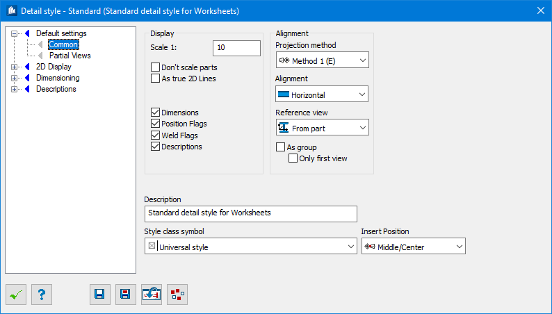
| Scale 1:
|
Here, you set the scale of your details. Depending
on the selection under ‘Don’t Scale Parts’ either the part or the text size is
scaled.
Please remember the hints under 'General
Information - Scale and Dimension Styles' in DetailCenter.
|
| Don’t scale parts
|
The parts keep their original size and only the text
is scaled for output on a printer /plotter.
|
| As true 2D lines
|
The details are transformed into pure
AutoCAD®
line
diagrams. Intelligent properties of the 2D-details of course won’t be available
any more.
|
| Dimensions
|
Dimensioning texts and lines are attached according
to the settings entered in the Dimensiong tab.
|
| Position Flags
|
Position flags are attached according to the
settings entered in the Position Flags tab.
|
| Weld Flags
|
Welding symbols are attached according to the
settings entered in the Welding Symbols tab.
|
| Descriptions
|
Additional label texts are attached according to the
settings entered in the Additional Texts tab.
|
| Projection Method
|
Here, you specify the system according to which
the different part views (front view, plan view, top view, etc.) are aligned
towards each other.
- Method 1
(E) – The distribution of the views is effected according to DIN.
- Method
3 (A) – The distribution of the views is effected according to American
standard.
|
| Alignment
|
Here, you specify the alignment of the details at
detailing. At groups, the main part specifies the alignment of the whole group.
- Horizontal – The parts are aligned
horizontally when detailed.
- Vertical
– The parts are aligned vertically when detailed.
- Like
Model –
AutoCAD
aligns the parts during detailing according
to their WCS position, which means that a slanted support remains slanted.
|
| Reference View
|
Here, you indicate how the front view of a
component part has to be specified. The other views then derivate from this
front view.
- From
Component – The element coordinate system of the component part is used for the
determination of the front view.
- From
Global Views – The global views are used for the determination of the front
view.
- Outside
Model – The view from the outside into the model is used for the determination
of the front view.
- Individually per Part – The
individually fixed front view of a part is used for the determination of the
part’s front view. If it has not been defined, the element coordinate system
will be used instead.
|
| As Group
|
Single parts views are displayed according to the
views of the corresponding groups, if existing. The left view of a stiffener is
e.g. the view onto a plate (normally this would be the plan view), because the
left view of the group would show the stiffener in this way.
|
| Only first View
|
Only the first view of the part is displayed
corresponding to the group; all other views are tilted according to standard
related to this modified view.
|
| Description
|
Allows a description of the detail style to be
entered in order to give more information about its precise function.
|
| Style class symbol
|
Allows the detail style to be allocated to an
existing style class. The relevant icon is then displayed in the DetailCenter’s
selection list to enable the essential function to be identified more quickly
(e.g. detail style for individual parts, structural groups, etc.).
Selecting a style class has no effect on potential
use. If the style can really only be used in a limited set of circumstances,
the style class or the symbol cannot be changed.
If you subsequently replace the style with a
restricted-use style, that style will receive the type of the currently
selected style class and will be usable for that object type only.
|
| Insertion position
|
This is used to enter the location at which detail
blocks are subsequently to be inserted. Select one of 9 distinctive insertion
points, from Top-Left to Bottom-Right, to which the detail block (including for
the 2D update) is to be anchored.
|