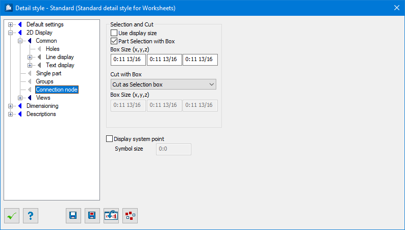
| Use display size
|
Uses active display size to display gusset
connection nodes.
|
| Part Selection with Box
|
When checked, all component parts situated within
the indicated box are depicted. Otherwise, only the parts belonging to the main
connection of the gusset are displayed.
|
| Box Size (x,y,z)
|
Enter the size of the selection box in the input
fields X, Y and Z. The distances refer to the component part coordinate system
of the main shape and are measured from the center of the main connection.
|
| Cut with Box
|
Here you select the distance to be used for cutting
the depicted shapes.
- At
Selection Box – The selected parts are cut off at the borders of the selection
box.
- At Cut
Box – The selected parts are cut off at the individual borders of a cut box.
Note: The result
will be that e.g. the supports are depicted a little bit longer, but no other
component parts of this extended area will be depicted.
|
| Box Size (X,Y,Z)
|
Enter the size of the cut box in the input fields X,
Y and Z. The distances refer to the component part coordinate system of the
main shape and are measured from the center of the main connection.
|
| Display System Point
|
The system points (work points) of the involved
connection shapes are depicted.
These are the points of intersection between the
center lines of the individual connection shapes and the main shape such as
e.g. a support.
|
| Symbol Size
|
Here, you enter the symbol size.
|