Symbolic display
If the display version "Single Line" is selected, you can also obtain a symbolic display for bracings and moment connections in addition to display as a single line. This is often used in the U.S. for the top view of vertical bracings and strut layouts.
The advantage of this representation is that the key information is contained in the symbols, but the drawing is simplified.
Assignment of components
The assignment of components to a display group is possible via a joint selection of the components concerned. In the component selection select Bracing connection elements to select a complete bracing element and Moment connection elements to select a complete moment connection element.
To enable correct recognition of the components, the latter must be modeled with the corresponding functions ("Structure object bracing connection element" for the bracing elements and/or "Moment connection element" for the moment connections).
Symbols for bracing elements
Bracing elements are represented by different symbols according to their construction. You have the choice between type A (slanting) and type B (straight), whereby a fixed line length should be used for type B, should the direction be represented for individual rods.
If the bracing element lies above the view level the symbol is always represented above and/or left of the vertical bracing level. The beginning of the rod as a symbol is always the nearest point to the view level. The length of the lines and distances can be defined in the general specifications for views (see "symbol dimensions").
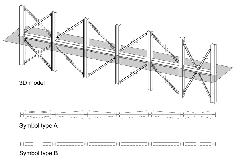
Symbols for moment connection elements
Moment connection elements are represented by a triangle at the end of the horizontal steel girder. The size of the symbol can be specified with the general specifications for views (see "symbol dimensions").

Primary and secondary view
A special rule applies to the display settings for the primary and secondary views of these object groups. This particularity can of course be used here too, for example to show a bracing for real in the front view but only as a symbol from the top.
If this entire object group is assigned, the selection is always determined by the parts to which elements are attached and not by the assigned parts themselves. If, for example, at least one column appears in the secondary view, this is the secondary view for the bracing as well.
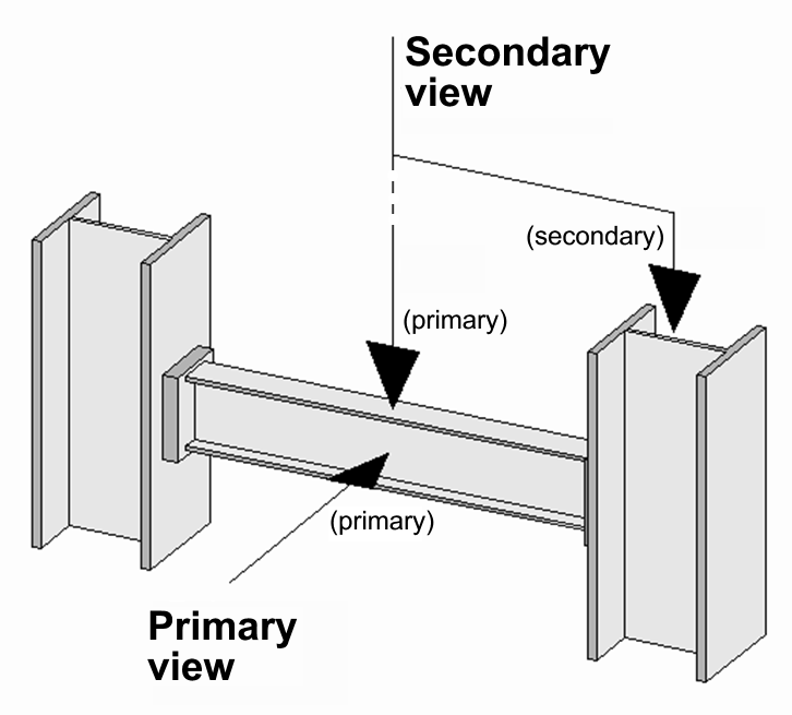
The figure illustrates the end plate connections between a horizontal beam and two vertical columns. The view from the top and the front view (i.e. the 2D plan) would not show any difference in the way this image is displayed, since the horizontal beam is always displayed in its primary view.
A difference can however be drawn based on the columns (since elements are attached to them), as the columns appear as primary or secondary depending on the view.