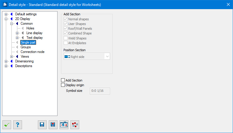
| Normal Shapes
|
Additional cross-sections are added to the views of
standard shapes.
|
| User Shapes
|
Additional cross-sections are added to the views of
special shapes.
|
| Roof/Wall Panels
|
Additional cross-sections are added to the views of
roof-wall-shapes.
|
| Combined Shapes
|
Additional cross-sections are added to the views of
combi-shapes.
|
| Weld Shapes
|
Additional cross-sections are added to the views of
weld shapes.
|
| At Endplates
|
In the plan view of a base or end plate, the
cross-section of the welded shape is displayed.
|
| Position Section
|
In the selection list, you define on which side of
a partial view the cross-section of the shape has to be displayed.
- Left
Side – The additional cross-section is displayed on the left.
- Right
Side – The additional cross-section is displayed on the right.
|
| Add Section
|
When checked, displays the direction symbol of
benchmark available in the group main parts.
|
| Display Origin
|
The zero point reference of coordinate dimensioning
of the single part is displayed as reference point or at American dimensioning
option as special symbol for Running dimensions.
|
| Symbol Size
|
Here, you enter the size of the symbol. This is the
size of zero reference.
|