ProStructures Help

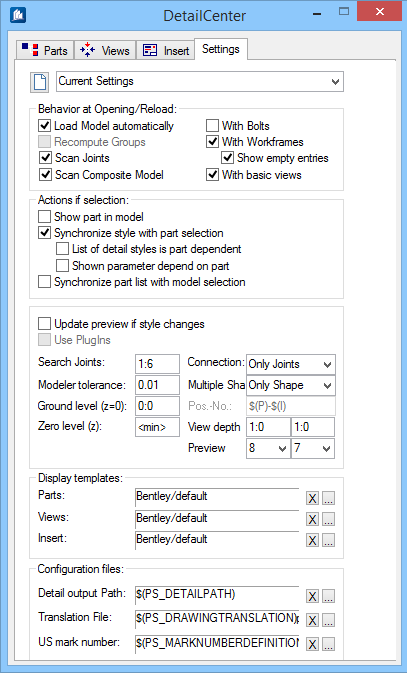
Detail Center - Settings tab

Used to set up options and preferences for the Detail Center.

In addition to the settings of the different work levels, you can use this tab to make the fundamental settings of the Detail Center. However, you will also find special default settings, which are valid for several work levels at the same time and which are set centrally.

Note: Many of the options described below are more applicable to structural steel and assembly drawings than to cast in place concrete and rebar elements.
SettingDescription
Open Template Manager Opens the Template Manager. This allows you to save your Detail Center settings in a template or to select and apply an existing template.

In this template, the individual settings of all work levels as well as the global settings are saved. Display sorting and filters can only be processed by indicating the corresponding templates in the global settings of the Detail Center. When you have defined one of the templates as "favourite", this allows fast selection from the neighbouring selection list.

Behaviour at Opening/Reload
SettingDescription
Load Model Automatic Scans the current drawing and builds a parts list. When the Detail Center is opened, the model is automatically analyzed and the component part structure is displayed according to all default settings in the component parts list.
Note: Since this process may require some time in the case of big models, this function can be deactivated. You also can select the analysis of the model structure manually at a later moment via the Update button in the component parts list.
Recompute Groups Calculates group properties when building the parts list. The group dimensions are calculated anew when the model structure is analyzed.
Note: If you created e.g. a parts list before and the data therefore are current data, you may reduce loading time of the Detail Center by switching off this option.
Scan Joints Scans groups of connections (joints) when building the parts list. When the model structure is analyzed, the gusset points of the construction (e.g. several connections) are also displayed as entries in the component part list.
Scan Complete Model When the model structure is analyzed, all reference files will be displayed as well.
Note: This can have an impact on model loading and general performance of the Detail Center, so it should only be used if the reference file display is necessary.
With Bolts Includes bolts in parts list (ProStructures). When the model structure is analyzed, all bolts of groups existing in the component parts list will be displayed as well.
Note: This allows an easy check of the used bolts, but the resulting great number of parts has a negative effect on the speed. This setting doesn't, however, influence the information about the bolts in-group details.
With Work Frames Includes the views that you specified when creating the work frame in the parts list. When the model structure is analyzed, the view levels of the working areas are also displayed as entries in the component part list. Normally, only planes are seized which also contain ProStructures component parts.
Show Empty Entries Includes all views in the parts list, even if they do not contain relevant parts. The view planes containing no ProStructures component parts are seized as well.
Note: This option should be used when a master drawing is used the component parts of which are exclusively integrated via references .
With Basic Views Includes ground plan, top view, and anchor plan in the parts list. When the model structure is analyzed, horizontal projection, plan view and anchor plan are also displayed as entries in the component part list.
Actions if Selection
SettingDescription
Show Part in Model Highlights members of a selected entry in the 3D model. The part (or complete groups) clicked in the list is (are) highlighted in the model. When another entry is selected, marking switches over to the new part.
Synchronize Style With Parts Selection Filters the style list based on styles used for the currently selected part. The program selects exactly the detail style the currently checked entry has in the component part resp. views list. When the dialog window for processing of detail style parameters is open, the corresponding settings are also directly displayed there.
List of Detail Styles is Part Contents of the detail style lists is dependent on the selected part type and the selection classes of the detail styles. The detail styles displayed in the component part list depend on which type of part is checked. If you have checked for example a single part, only the styles classified for single parts will be displayed.
Note: Style classification is effected in detail style dialog. The result is that only the styles appropriate for the component part or function will be displayed later.
Shown Parameter Depend on Part Detail Styles screen displays only the pages that are used for the current part type. The displayed parameter pages in the detail style dialog depend on the type of the checked component part. If you have e.g. checked a single part, the pages for groups will not be displayed.
Synchronize Part List With Model Selection Automatically rebuilds the parts list when you switch to a different drawing. The Detail Center is always updated to match with the active model drawing, if several drawings are open. Since this process may require some time, you can switch off this option in the case of big models. Update can be selected manually via the Update button in the component parts list.
Note: In addition, you often don't want to update the lists while you are only looking up something in another drawing.
Update Preview if Style Changes Updates 2D preview to reflect changes to the active default style. The preview of a detail is automatically updated when you modify a parameter in the detail style dialog window. In case of many modifications, it is however reasonable to deactivate the update first and to select it manually afterwards.
Use PlugIns Uses third-party plug-ins if applicable.
Search Joints Sets the Maximum distance between two connections to create a joint (group of connections). The maximum distance up to which the different single connections (these are recognized via the logical links) are combined to a connection gusset.
Connection When using the Search Joints option, select identify joints as Only Joints or As Structure from the drop-down list.
Modeller Tolerance Sets et the tolerance for contour calculation of the modeler. Calculation tolerance value used for the modeller.
Multiple Shape When using the Modeller Tolerance option, select identify joints as Only Joints or As Structure from the drop-down list. The option determines how combined weld shapes are displayed.
  • Only Shape – Only the entry for the complete weld shape is displayed.
  • As Structure – The entry for the complete weld shape is displayed and, subordinate to this shape, the single components, too.

    Thus it is easy to check out of which components the shape consists. In addition, it is possible to create each single component individually as a detail.

Ground Level (z=0) Indicates the offset distance that is added to the measured elevation height when you use elevation flags. Sets the height (z-coordinate) the plane for the plan view and for the anchorage plan has to be laid in the model (world coordinates). When you indicate the value <min>, the deepest point which exists in the model will be taken.

The effect will be that any concrete foundations beneath supports existing in the model don't have an influence any more

Pos. No. Sets the Position Number format of a multishape component if an individual number is not assigned. It is a general format template for the position number of weld shape components. This number is used as an alternative, if there isn't any position number known from the 3D-model

Format variables include: $(P) Position Number Multiple Shape; $(I) Numeric Index; $(Ilz) Numeric Index with Prefixed 0; $(Ilc) Index Lowercase; $(Iuc) Index Uppercase.

Zero Level (z) Indicates the absolute Z coordinates for the zero level in the model. Sets the height (z-coordinate) the plane for the plan view and for the anchorage plan has to be laid in the model (world coordinates). When you indicate the value <min>, the deepest point which exists in the model will be taken.

The effect will be that any concrete foundations beneath supports existing in the model don't have an influence any more.

View depth Upper and lower clipping plane distances for part selection on the ground level. Set the distances for the plan view plane and for the anchorage plan of the sectional area.
Preview Allows you to preview any number of times without switching design models, hence eliminating the need for re-scanning objects by the DetailCenter.
Note: Two separate default view settings are provided for previews (left Preview field) and manual detail creation (right Preview field), they are initially set to view 8 and 7
Display Templates
SettingDescription
Parts Sets the template for display sorting in the Parts List. it is the desired template for sorting and filter of the component parts list.
In the display field, the currently selected template is displayed. Click on the small button (...) on the right side of the display to select another template. Click on the small button (X) to reset the display to standard display.
Note: Only the templates you created before via display sorting of component parts list will be offered for selection. If, in the mean time one of these templates has been changed, the modified display will be shown, too
Views Sets the desired template for display sorting and filter of the views list. Selection is analogously to the one for component parts list.
Insert Sets the desired template for display sorting in the Insert List.
Configuration Files
SettingDescription
Detail Output path Output directory for Detail Center. Indicates the complete path of your current project in the case that project management is used. If other displayed paths are further subordinate directories of this project path, the corresponding part is only displayed there using the config variable .
Translation File Current translation file for drawing text, labeling.

In the display field, the currently selected file is displayed in terms of config variable. Click on the small button (...) on the right side of the display to select another file. Click on the small button (X) to reset the display to standard default

US Mark Number Current description for US mark numbering. The definition file used for US-mark numbers. This file includes the format description of the numbers. Selection is analogous to translation file.