Detail Center - Parts tab
The Parts tab is used to:
- view a list of parts and views for your model
- select, create, or modify detail styles
- assign views or parts to the desired detail styles
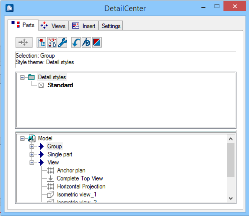
When selecting the Detail Center command, this tab will always be active first, and the current drawing is scanned by the Detail Center. All model parts are searched according to predefined criteria and then displayed. This might take some time when large models are involved. All detail styles are also searched and displayed.
A great number of the described functions may be selected via the context menu of the right mouse button. Look there whether the corresponding entry is available if there should be no hint in this documentation. If you need only a section of a model, use the visibility classes to hide the unneeded parts. Any parts hidden with the visibility class command are not recognized by the Detail Center. Please note however that these parts are then no longer recognized by any of the details.
| Setting | Description |
|---|---|
 Create Views Create Views
|
Move all selected parts on the view page and create all necessary views. Imports all parts selected in the parts list into the view list and determine the views pre-selected in the detail style. Component views can be generated only for parts linked with a detail style. |
 Recursion Toggle Recursion Toggle
|
Switch recursion on or off. If recursion is on, and you select a parent topic, all associated child topics are automatically selected. Any processing applied to a parent entry is also applied to all subordinate child entries. When recursion is off, only the selected entry is selected or processed, or all entries on the same level can be selected if this option is activated in the model. |
 Display Settings Display Settings
|
Change display options and filters for the Detail Center. Opens the Settings for Display dialog, which is used to display sorting of component parts list. Here, you can select the standard display or an individual structure and set user-defined filters. |
 Special Settings Special Settings
|
Set up special settings when working with the active model. Opens the dialog for the work tools where you can specify additional settings only for this work level. Depending on the work level, the global settings are valid, too, which can be defined separately. |
 Reload Reload
|
Reload all parts from the drawing, and update the display. Searches the selected drawing once more. This is required if you activated a different drawing in the MDI environment or if changes were made to the current drawing (e.g. new position). |
 Detail Center Express Detail Center Express
|
Opens the Detail Center Express Wizard. The Detail Center Express used to carry out a complete detailing according to a specified pattern. |
 Revision Center Revision Center
|
Manage revisions (Working With the Revision Center) to details and drawings. Launches the Revision Center. From here you can manage all drawings and modifications generated, plus additional documents, from the model. The Revision Center can also be run without the Detail Center as an independent module. |
| (Information area) | Displays the active detail style and part/view. The info line details drag-drop actions. |
| Detail Styles area | This list displays all available detail styles. The
selection consists of the styles saved in the drawing as well as the style
files saved on your local or network drive.
You can classify the detail styles available in as many groups as necessary using the 'detail style themes' and thus organise them thematically. A symbol also makes it easier to find the appropriate style for a given construction type |
| Parts List area | Displays all parts of a model. This is the primary
working list of the Detail Center. Display and sorting of the list depends on
the display settings.
Small icons display in front of most parts. If an icon does not display, the object is a parent sorting entry and cannot be detailed. Part icons can display in the following colors:
|
2D drawing generation and updating with hidden '***' parts
In previous versions, the views or groups listed in the DetailCenter with " *** " would alert/warn you when one or more object(s) of a view or group are hidden and cannot be processed or updated.
Earlier, when one or more Steel or Concrete object(s) (this rule does not apply to rebar) either in the active view of a model or in a reference file are hidden, associated views or groups are then flag with "***" in the DetailCenter, alerting/warning you that one or more object lying within the ProStructures view or subpart(s) of a group are hidden and not visible, nevertheless they can be processed and can be updated, as you decide.
Only the following hiding methods to steel and concrete object(s) (this rule does not apply to rebar) are supported by the DetailCenter for views and groups drawing generation, all other methods are ignored:
It is important to note that for groups:
- When a subpart of the group is hidden the *** will display next to the group.
- When the main part of a group is hidden, the complete group is not listed in the DetailCenter.
Active model:
- Hide
- Hide Group
- Hide Except
- Hide Except Group
- Hide At Plane
- Hide At Plane Except
- Display Class
- Area Class
- Level Freeze
- Level Display off
Reference model (from within a composite model)
- Level Freeze
- Level Display off