Construction Axes in Overviews
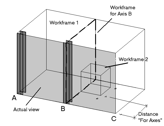
The figure below shows the connections between current view and construction axes.
In the current view (gray) of work area 1 the construction axes A, B and C would be displayed. The corresponding work frames contain the information about axis description and text display. As, however, the construction axis C is situated outside the displayed construction, it could be hidden with the Axes only within option.
The axes of the small work area 2 would only be displayed if the smallest distance of the corresponding relevant work frame was smaller than the preset value of ‘Max. Distance’ for the visual depth.
If different values have been indicated for the left and right axis description, the description is used which is next to the current view.
View depth
The view depth for a view, i.e. which parts can be displayed, is defined based on the intersecting distances in the working area or the settings of the detail style. If an object lies outside the zone parallel to the plane of projection, it cannot be displayed. A distinction is drawn here between normal view depth and extended view depth, e.g. for bracings.
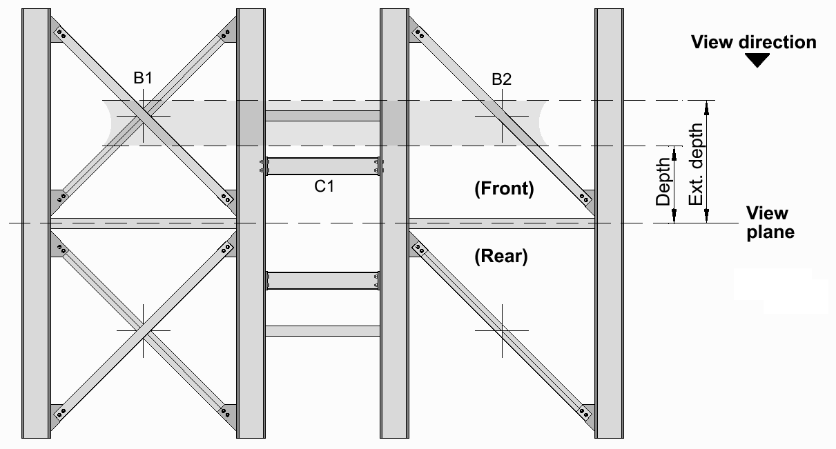
The following illustration shows the relationships between the current plane of projection, the direction of projection and the view depths:The parts of the bracing B1 and B2 can be included in the view from above in their entirety under the settings for the view, since their structural elements (crosses) lie within the extended view depth. This enables all parts of a bracing to be displayed or faded out – regardless of whether only individual parts lie within the normal view depth.
At least one part of the bracing must however lie within the normal view depth, since this depth takes first priority.
Displacement of Reference Plane
The reference plane of the depiction can be displaced towards the corresponding work frame by an additional value. Thus you can get a more suitable display especially in case of intersections without having to generate a separate view frame.
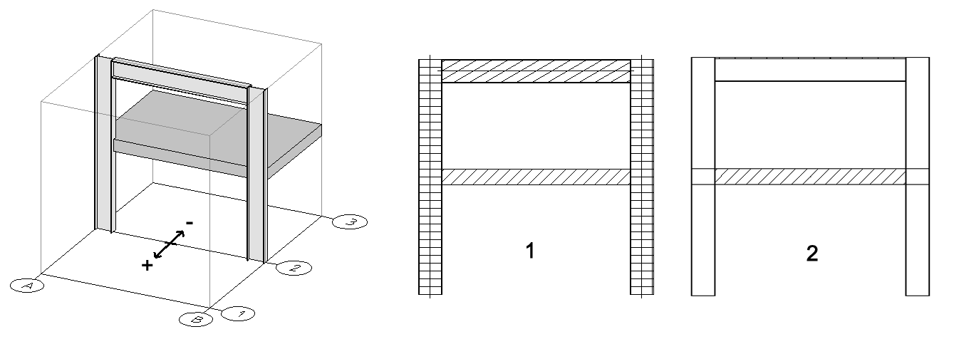
In the example below, the intersection view has to be generated at the constructional axis 2. As all shapes are situated centrally, the result would normally be a depiction like (1), because the shapes of the web are cut, too. When you enter a small value for displacement, the intersection plan can be situated outside of the web, and only the roof of the building gets a visible shading.
Connection Details and Cranked Views or Cuts
In addition to standard views on work areas, ProSteel can also generate cranked views and detail point overviews (connection details). The kind of view is determined by the kind of work area defining the view.
Typical connection details can alternatively be generated automatically if connections with named logical links are available at the corresponding position. Please also refer to Connecting Gusset or Gusset Details.
If a depth has been indicated for the work area, it is a matter of detail point overview allowing you to display several views on this area simultaneously (front view, plan view, etc.). Detailing is effected like that of a standard overview, i.e. all parts are exported as AutoCAD® lines and dimensioned according to the settings for overviews.
If a cranked cut has been inserted, you can display a cut though the model which is situated in different levels. You can hide undesired sections or refrain from an additional view. Depending on the position of the cutting line, the parts are cut or displayed as view.
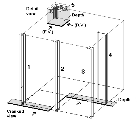
The neighboring figure shows you the different variants:
- The standard front view shows the supports 1, 2 and 3 as view unless the visual depth of the work area reaches up to support 4.
- The cranked view only shows the supports 1 and 4 in the area of the indicated visual depth. If there were parts on the thick, black cutting line, they would be displayed as cut.
The detail point overview shows the construction 5 in the selected views (here front view and view from the right), the cutting depth results from the corresponding 3rd dimension of the cube.
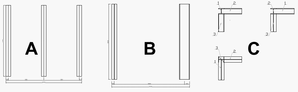
Detail Style
The result of detailing process for the different kinds of overviews is displayed in the following figure. The display of dimensions, position flags, etc. depends on the selected detailing style. Example (A) shows the standard view, example (B) the cranked view and example (C) a detail point overview consisting here of three partial views.