| Automatic Selection
|
The program automatically displays the required
views according to the existing detailing processes of the part. Thus, all
detailing processes can be displayed and dimensioned.
In addition, you can add the basic views, one or
more global isometric views and the unfolding (only in case of bent plates).
These views will be used in any case.
|
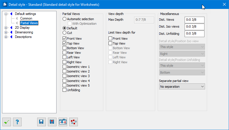
| Default
|
You can choose the views to be generated from the
six existing basic views. In addition, you can add one or more global isometric
views and the unfolding (only in case of bent plates).
Here, you also pre-set the desired views for the
overviews of detailed points; for standard overviews, however these settings
haven’t any meaning,
|
| Cut
|
A cut is made in this view frame for any model views
you like. Position, cut depth and displayed parts are determined by means of
this frame.
|
| View selections
|
Here, you pre-select which views have to be created
during the detailing process. In the DetailCenter, you also have the
possibility to delete views or to add further views.
|
| Max. Depth
|
Here, you can indicate a visual depth up to which
the subparts are seized at construction group display. This filter can be
switched on separately for the different views to limit the depth only at left
and right views.
|
| Limit View Depth
|
When displaying construction groups, the visual
depth for the selected view is limited to the value specified under 'Max.
Depth'.
Please note, however, that unlike cut areas at
views nevertheless the complete component part will be displayed. The
specification of this value only serves as depth filter for seizing of the
complete component part.
|
| Dist. Views
|
Here, you specify the distance of the basic views
incl. dimensions and text towards each other if several views are to be
generated within one detail block.
|
| Dist. Iso Views
|
Here, you specify the distance of the isometric views
towards the basic views and towards each other.
|
| Dist. Unfolding
|
Here, you specify the distance of the unfolding of a
bent plate towards the basic views.
|
| Detail style/Position Iso
|
If need be, you specify another detailing style here
with which an isometric view has to be depicted. If you indicate ‘This Style’,
no separate detailing style will be used.
|
| Detail style/Position
|
Here, you specify the position where the isometric
views have to be depicted with reference to the basic views. They can be
positioned above, below, on the left or on the right side of the basic views.
|
| Separate partial view
|
Select if a separate partial view is to be used for
concrete reinforced objects.
|