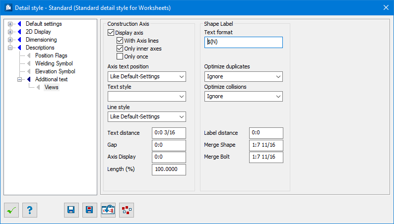
| Construction Axis
|
Options for setting construction axis attributes.
|
| Display Axis
|
Displays the axes descriptions of the work frames
perpendicular towards the current view. Text sizes and display form are adopted
from the work frame properties.
|
| With Axis Lines
|
The actual axis is also displayed as 2D-line in the
corresponding view.
|
| Only Inner Axes
|
Only those axes are displayed which are situated
within the determined overall dimensions of the view including a snap range.
|
| Only once
|
Displays the axes only once
|
| Axis text position
|
Determines the axis text position, either one of the
corner or per standard style -Like Default-Settings.
|
| Line style
|
Sets standard style template, like default-settings
template is selected here.
|
| Text Distance
|
Here, you enter the distance of axes label towards
the last outer dimension chain.
|
| Gap
|
Sets the gap between axes labels and parts.
|
| Size
|
Sets the size of the display axe.
|
| Axis Display
|
Here, you enter a snap range up to which the axes
situated outside the overall dimensions are still displayed.
|
| Length (%)
|
Here, you enter the relative length of the axis line
(in %) related to the overall dimensions. Normally, the axis line is running
towards the outer edges of the display (= 100%). If you enter a value bigger
than 100, the line will be extended over these edges. If you enter a value
between 1 and 100, the line will only partly be displayed from the bottom resp.
from the left, e.g. to hint only at it in views.
|
| Shape Label
|
Settings for shape labels.
|
| Text Format string
|
Here you can input a format template composed of
fixed and variable text components for labeling parts. The various placeholders
$(…) are thus replaced with the current values of the respective part.
Possible placeholders:
$(N) Name
$(Ns) Short Name
$(P) Position number
$(S) Shipping number
$(M) Material description
$(E) Elevation distance to view plane
$(R1) Note 1
$(R2) Note 2
$(X, etc.) Special treatment of empty texts
Additional data fields are supported in the Text Format, where you
can easily pick required Data field and can align with object. They are:
$(PG) Group Position Number
$(PA) Assembly Position Number
$(AC) Area Class
$(TN) Total Count
$(DC) Display Class
$(FC) Part Family Class
$(LN) Length
$(WG) Weight
$(SX) $(SY) $(SZ) Start X | Y | Y
$(EX) $(EY) $(EZ) End X | Y | Y
$(IX) $(IY) $(IZ) OInsert X | Y | Y
\n Add new line
|
| Optimize Duplicates
|
Determines method to optimizing equal labels that are found
inside a maximum range.
- Ignore
- Delete Label
- Merge and delete
This is considered as a 1st step of optimization.
|
| Optimize Collisions
|
Determines method to optimizing colliding labels that are found
inside a maximum range.
This is considered as a 2nd step of optimization.
|
| Label Distance
|
Sets minimum distance between label and object border (0.0 by
template).
|
| Merge Shape / Merge Bolt
|
Sets the vale that merges the shape and bolt
annotation with shape labels.
|