| Basic View
|
The overview is displayed as standard 2D-depiction
where all hidden edges are correctly determined.
|
| Anchor Plan
|
An anchor plan with alternatively two different
scales is generated. Display of the base plates can thus be depicted in an
enlarged display.
|
| Details Sc 1
|
Here, you enter the scale of base plate details in
the anchor plan. However, an anchor plan can only be generated if you have
linked the view Anchor Plan in the component parts list with this style
setting.
|
| With Columns
|
In addition to the anchor details, the columns are
also displayed as cross-section.
|
| Columns As Object
|
The columns in the anchor plan are displayed as
intelligent 2D-Objects.
|
| Insert Edge
|
Here, you specify the distance the beginning of the
sketch drawing has to have from the insertion point of the shape. If you
indicated a relative length smaller than 100%, this is also the beginning of
the center line.
|
| Relative Length
|
Here, you specify the length of the sketch drawing as
relative value related to the shape length. The rest will only be displayed as
center line.
|
| Use
references
|
The parts added to the model via
references are displayed and dimensioned
as well. The above mentioned display filters are also valid for these component
parts.
|
| Parts as Objects
|
Parts are treated as objects in the view.
|
| 2D grouping per object
|
Enables selectable 2D output as grouped objects.
|
| Workframe Boundary
|
Sets effect of workframe boundary rectangle.
|
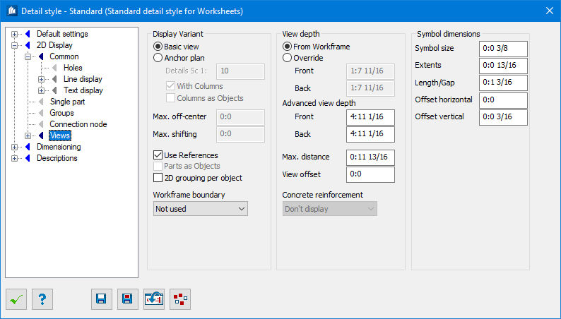
| From Workrame
|
The view depths assigned to the work frames are used
for views.
|
| Override
|
The view depths specified in this dialog are used for
views.
|
| Front/Back
|
Enter the view depths Front and Back, which have to
be used for the views.
|
| Advanced view depth
|
Provides an extended view depth for the purpose of
identifying bracings (where these are controlled via a separate structural
element). See also View depth in this chapter. If the structural element is
located within this area, all parts it contains will be affected provided that
at least one part falls within the normal view depth.
|
| Front/Back
|
Used to specify the visual depths Front and Back to
be used for the extended view depth.
|
| Max. Distance
|
Enter the maximum distance another work frame is
allowed to be removed from the current view to be interpreted there as
construction axis for axis display and dimensioning.
|
| View Offset
|
Enter a displacement the plane used for the view
has to have from the actual work frame (in view direction).
If the view plane doesn’t have to be exactly in
the work frame plane, this will save you an additional view.
|
| Concrete reinforcement
|
Here you specify which reinforcement objects are to
be represented in the view if a component contains reinforcing objects.
- Do not display
– no reinforcement is used.
- Entire object
–all reinforcement objects of the component are used, even if these already are
outside of the field of vision.
- Use view depth
– only those reinforcement objects of a component are used which are also
within the field of view.
Note: This only
pertains to a preselection which you can additionally limit. Further details
are found in ‘ProConcrete`.
|
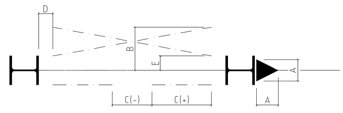
| Symbol dimensions
|
If you use the ‘Single Line’ part display mode,
specific object groups can be displayed in the form of symbols. See also under
Displaying as symbols in the Displaying parts chapter.
|
| Symbol size
|
The size of the symbol for moment connections.
(A)
|
| Extents
|
The maximum extension for symbols for bracings,
where symbol type ‘A’ has been selected.
(B)
|
| Length/Gap
|
The line length for symbols for bracings. Negative
values determine the spacing between two symbol lines.
(C)
|
| Offset horizontal
|
The inward horizontal offset when bracings are
displayed as symbols.
(D)
|
| Offset vertical
|
The outward vertical offset when bracings are
displayed as symbols.
(E)
|