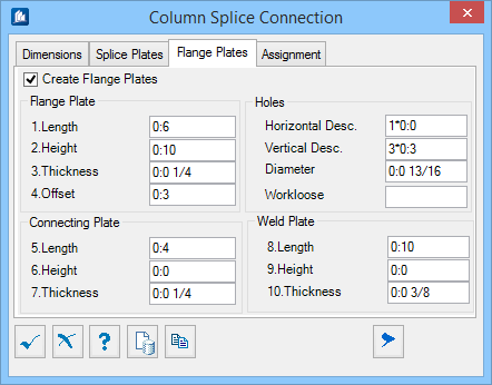
| Create Flange Plates
|
When checked, places flange plates vertically along the outer
edge of each flange. When unchecked, only the transition plates are created.
|
| Flange Plate
|
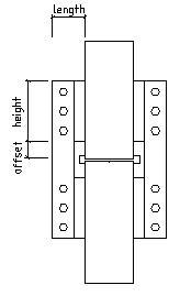
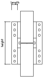
- Length – Sets
the flange plate dimension in a direction parallel to the cross-sectional X
axis of the shape selected. A positive value determines the length. A negative
value or value of 0 is not permitted. The default is 135 or 5.25 depending on
the units setting.
- Height – Sets
the flange plate dimension in a direction parallel to the shape direction of
the shape selected. A positive value determines the length. A negative value or
value of 0 is not permitted. The default is 250 or 10 depending on the units
setting.
- Thickness –
Sets the flange plate thickness. A positive value determines the thickness. A
negative value of value of 0 is not permitted. The default is 5 or 0.1875
depending on the units setting.
- Offset – Sets
the offset between the end of the shape and start edge of the flange plates
along the direction of the shape. A positive or a negative value makes the
offset upward or downward. A value of 0 indicates no offset. The default is 70
or 2.75 depending on the units setting.
|
| Connecting Plate
|
- Length – Sets
the connecting plate dimension in a direction parallel to the cross-sectional X
axis of the shape selected. A positive value determines the length. A negative
value or value of 0 is not permitted. The default is 90 or 3.625 depending on
the units setting.
- Height – Sets
the connecting plate dimension in a direction parallel to the shape direction
of the shape selected. A positive value determines the length. A negative value
is not permitted. A value of 0 sets the height of the connecting plate to the
extents of the flange plate. The default is 0.
- Thickness –
Sets the connecting plate thickness. A positive value determines the thickness.
A negative value of value of 0 is not permitted. The default is 4 or 0.125
depending on the units setting.
|
| Holes
|
Optionally creates a rectangular pattern of holes in the
connecting plate. The rectangular pattern is centrally positioned on the plate
and is defined used Hole Field descriptions.
Hole Fields descriptions are defined by entering
Number*Pitch of Holes with an optional
intermediate pitch (separated by a comma ',').
Example:
number1*pitch1 [,intermediatepitch1[,number2*pitch2 ...]]
- Horizontal
Desc. – Sets the description of the horizontal hole field in a
direction parallel to the connecting plate length direction. The Default is 1*.
- Vertical
Desc. – Sets the description of the vertical hole field in a
direction parallel to the connecting plate height direction. The Default is
3*75 or 3*3 depending on the units setting.
- Diameter – Sets
the diameter of the holes in the connecting plate. Default is 22 or 0.875
depending on the units setting.
- Workloose –
Sets the allowance for the hole workloose for the hole in the plate. A positive
value determines the workloose.
|
| Weld Plate
|
- Length – Sets
the weld plate dimension in a direction parallel to the shape direction of the
shape selected. A positive value determines the length. A negative value or
value of 0 is not permitted. The default is 250 or 10 depending on the units
setting.
- Height – Sets
the weld plate dimension in a direction parallel to the cross-sectional X axis
of the shape selected. A positive value determines the height. A negative value
or value of 0 is not permitted. The default is 30 or 1.25 depending on the
units setting.
- Thickness –
Sets the connecting plate thickness. A positive value determines the thickness.
A negative value or value of 0 is not permitted. The default is 6 or 0.25
depending on the units setting.
|