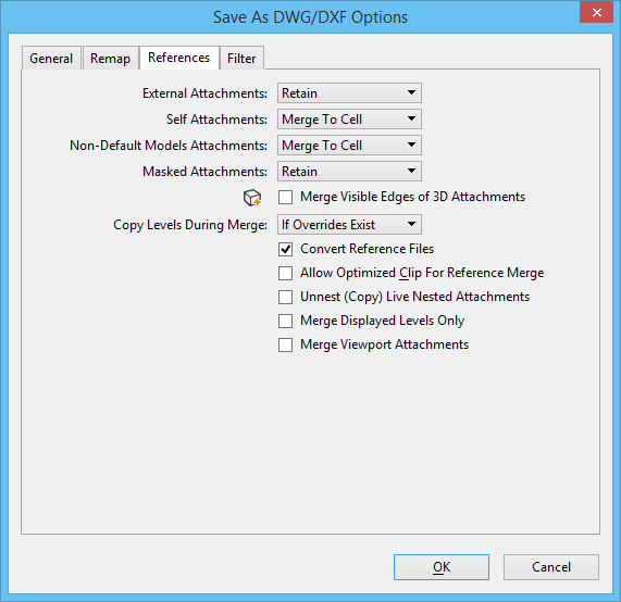
Save As DWG/DXF Options Dialog, References Tab
Controls how references are handled when you save a DGN file to a DWG or DXF file. Opens when you select , select AutoCAD Drawing Files (*.dwg) from the Save as Type list, click the Options button, and click the References tab.
The DWG file format does not support all the reference attachments possible in ProStructures.
You can control how external, self, non-default model, and masked attachments are handled when saving to DWG or DXF. You can select a different setting for each type of attachment. However, if you do that, the following rules apply:
- If the External Attachments and Masked Attachments list boxes are set differently, then the one that uses the setting with the highest priority takes effect. The settings have the following priority, from highest to lowest: Omit, Merge to Cell, Merge, Retain.
- If either the External Attachments or Masked Attachments list box is set to Omit, then all attachments will be omitted, regardless of the other attachment type's setting.
- If the Self Attachments and Masked Attachments list boxes are set differently, the Self Attachment setting takes priority.
| Setting | Description |
|---|---|
| External Attachments | Controls how standard attachments to the default model are handled when you save a DGN file to a DWG/DXF file. Generally, it is better to retain these types of attachments as XREFs (the default). You can also choose to merge the default model and its attachments into a single file.
|
| Self Attachments | Controls how self-attachments are handled when you save a DGN file to a DWG/DXF file. A self-attachment is a reference attached to itself. In ProStructures, self-attachments are often used to create detailed sections of a drawing. AutoCAD does not support self-attachments. You must merge self-attachments to preserve their display. |
| Non-Default Models Attachments | Controls how attachments of non-default models are handled when you save a DGN file to a DWG/DXF file. AutoCAD's support for multiple models within a file is much more restrictive than ProStructures's. AutoCAD is limited to one default model per file with one or more sheets ("paper space" models) displaying views of that model. AutoCAD's XREF attachments can only display the default model.
Note: This setting is ignored if Non-Default Design Models is set to Create Separate Files on the General tab in the Advanced settings.
|
| Masked Attachments | Controls how clipping masks in attachments are handled when you save a DGN file to a DWG/DXF file. Earlier versions of AutoCAD did not support XREFs with clipping masks. Since R2010, AutoCAD started supporting single clip masks, also known as invert clips. However, AutoCAD still does not support more than one clip on the same attachment. Therefore, saving a masked attachment to a DWG file (Retain) may remove any clipping masks applied to that attachment. When you use merging, the clipping masks are applied to the geometry as it is merged.
|
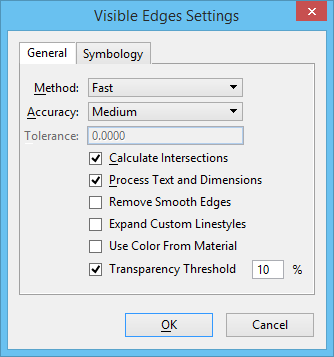
| Merge Visible Edges of 3D Attachments | If on, a 3D reference file attachment will have its visible edge representation merged into the master file. This setting affects all references except the ones that display wireframe geometry. This option is useful when using Dynamic Views because target formats such as DWG and V7 DGN do not support the dynamic view display options. To check the effect of this setting refer to the example in Merging References into the Active Model. If on, this setting overrides all attachment settings above it. When you turn on this check box, a Visible Edges Settings icon appears next to it. Clicking this icon opens the Visible Edges Settings dialog. The changes made in Visible Edges Settings dialog, when accessed from here, are saved in DWG settings, such that the next time you do a Save As DWG and have the Merge Visible Edges of 3D Attachments check box turned on, your previous visible edges settings are restored. |
| Copy Levels During Merge | Describes how levels are handled when you merge references from the DGN file into a DWG/DXF file.
|
| Convert Reference Files | If on, when saving a DGN file to a DWG file, all references are converted to DWG files.
|
| Allow Optimized Clip for Reference Merge | If on, maintains the surfaces and solids and shapes when they are clipped during the merge process. If off, the surfaces and solids are dropped to their boundary/wireframe elements. |
| Unnest (Copy) Live Nested Attachments | If on, nested attachments will be attached directly to the file. Note that, for DWG files, live nesting is turned on implicitly except for Overlay attachments. Because of this, unless the "Create Overlays For References" option also is selected, using this option may produce undesirable results. The "Create Overlays For References" option is located in the References section of the General tab. |
| Merge Displayed Levels Only | If on, levels displayed in the selected view are merged into the output file. If off, all levels are merged into the output file. Note: This setting is turned on and disabled if the configuration variable MS_MERGE_DISPLAYEDLEVELSONLY is set.
Note: Level Display in the Basic section of the General tab defines whether Global, or a selected view is used.
|
| Merge Viewport Attachments | If on, and if the Self Attachments option is set to Merge or Merge to Cell, all viewport attachments will be merged into sheet models. Many times, when merging viewports into sheet models, you may also want to turn on Merge Displayed Levels Only to retain the same visibility of the sheet model in the saved DWG file. If off, self-attachments of the default model into a sheet model will become a viewport entity when saved as DWG. This is the default behavior and in this case the Self Attachment option has no effect on the attachment. |