Single Brace A
 Used to parametrically generate a
connection between a brace member and a supporting member.
Used to parametrically generate a
connection between a brace member and a supporting member.
The Substation Gallery object connection is intended for use with triangular and rectangular substation trusses. This tool can also be used on any pipe or hollow HSS tube supporting shape providing that an offset distance between the connection shapes and the center of the support shape by the plate thickness has already been included.
This connection supports two back to back angles. It also supports plate alignment to the supporting shape center or optionally to the face of the connecting angle whenever the bracing plane is twisted or warped.
Accessed from: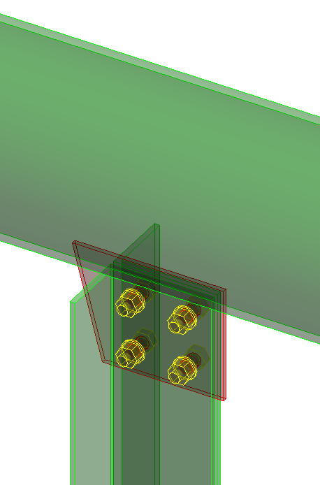
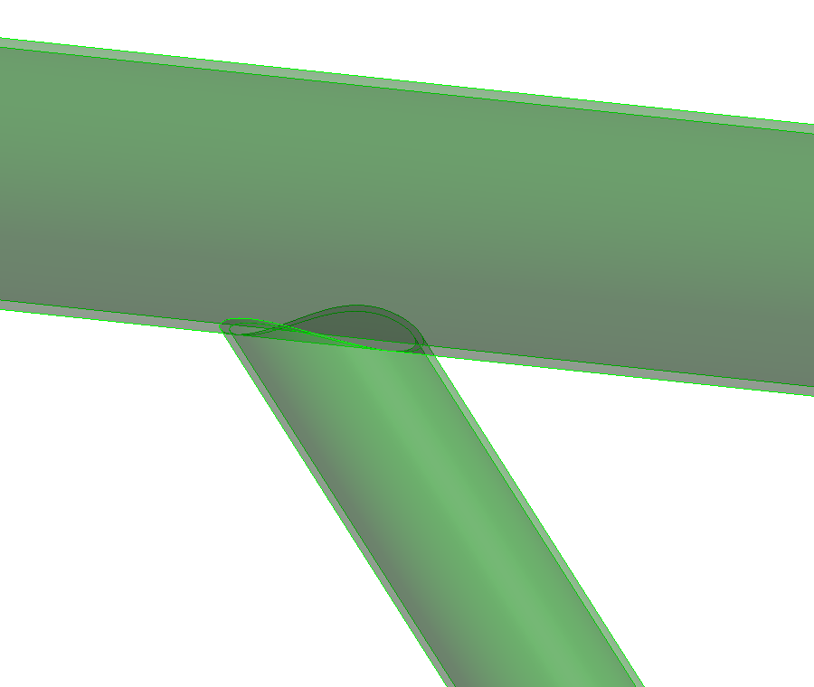
Plate tab
Used to define the connection type, connection orientation, and gusset plate geometry.
| Setting | Description |
|---|---|
| Welded | When on, a welded brace connection is created. Enables the Weld settings in the dialog's Bolt/Weld tab. |
| Thickness | Single, double and triple brace connections require brace members be correctly positioned, with a gap equal to half the eventual plate thickness from the supporting shape centerline. The plate thickness cannot be added or altered here, however the thickness is displayed as a reference. Denoted with 1 in the diagram. |
| Gap | Sets a gap between the brace and the supporting member. Denoted with 2 in the diagram. |
| Plate Offset | Sets the distance between the chamfer edge corner and the edge of the brace. Denoted with 3 in the diagram. |
| Distance to Chamfer Edge | Sets the distance between the chamfer edge and the center line of the closest holes. Denoted with 4 in the diagram. |
| Angle | When on, the side edge is angled by the angle entered in the value field. Denoted with 5 in the diagram. |
| Perpendicular Short Edge | When on, the short side edge of the plate is perpendicular to the supporting member. |
| Chamfer | When on, the long side edge is cut by the amount entered in the value field forming a chamfer. Denoted with 6 in the diagram. |
| Chamfer Perpendicular | When on, the chamfer edge is perpendicular to the supporting member. Enabled only when Chamfer is on. |
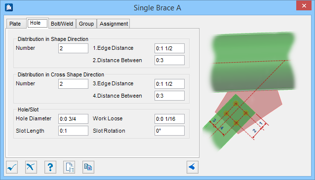
Hole tab
Used to enter bolt arrangement values for the brace.
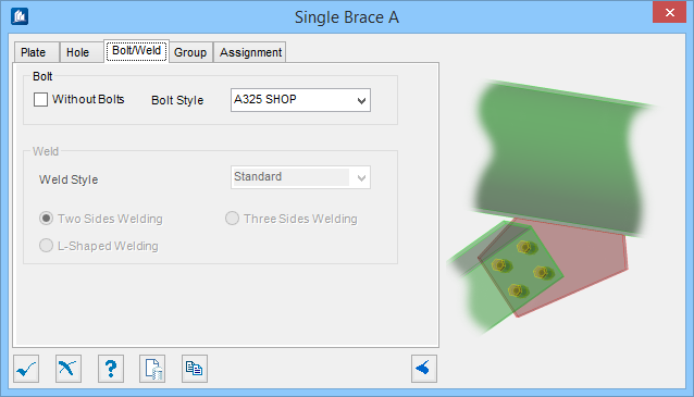
Bolt/Weld tab
Used to specify bolt and weld material data, as well as select the connection method used.
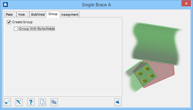
Group tab
Used to create a new ProStructures group with the Substation Gallery objects.
| Setting | Description |
|---|---|
| Create Group | Select this option to select additional shapes. Separate Substation Gallery objects are created. |
| Group with Bolts/Welds | Select this option to group bolts and welds. |
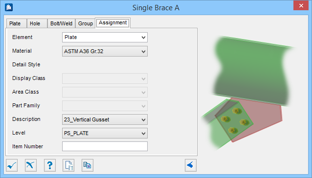
Assignment tab
Used to assign elements in the connection to a material, display class, area class, part family, level, etc.
Dialog Controls
| Setting | Description |
|---|---|
 OK OK
|
Closes the dialog and save your changes. |
 Cancel Cancel
|
Closes the dialog without saving changes. |
 Help Help
|
Opens online help. |
 Template Template
|
Saves and retrieve (Using Templates) settings to be used on other projects. |
 Clone Clone
|
Shifts focus to the geometry, allowing cloning the current structural object (stair, frame, truss, etc.) properties to match one or more objects selected in the view. |
  Show /Hide
Preview Show /Hide
Preview
|
Opens or closes, respectively, a flyout panel to display an illustration based on the tool. |