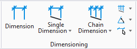
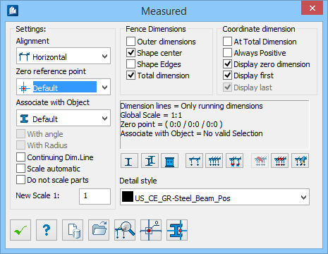
Measured
 Used to create dimensions for 2D
detailing.
Used to create dimensions for 2D
detailing.
| Setting | Description |
|---|---|
| Alignment |
Select the general direction of dimensioning from the drop-down list.
|
| Zero reference point |
Select which origin is used for alternative coordinate dimensioning.
|
| Associate with Object |
Here, you specify whether a reference part has to be used for dimensioning. This is necessary to evaluate shape shortenings correctly. However, the part has to be an intelligent 2D part’.
|
| With Angle | At arc dimension, the included angle is additionally entered as well into the dimension. |
| With Radius | At arc dimension, the reference radius is additionally entered as well into the dimension. |
| Continuing Dim. Line | A dimension chain can be built continuously by clicking on individual points. If this field is not checked, you have to continue dimensioning single distances and you can obtain a dimension chain with gaps. |
| Scale automatic | The settings for scale and object scaling are automatically determined by the global scale and by the reference part. If your work has been logical according to ProSteel (either un-scaled details and global scale for plot or scaled details and scale 1:1 for the plot), incorrect default settings are avoided. |
| Do not scale parts | The parts to be dimensioned are not scaled. Thus, the original measured lengths can be used. However, if the field has not been checked, all measured lengths are multiplied with the indicated scale under 'New Scale'. |
| New Scale | The scale used for converting the measured lengths
and text sizes depending on the settings for part scaling under ‘Parts Not…’
Here, you enter the same scale value used for object scaling when detailing. For example, the value 10 if you have selected the ‘scale 1: 10 with object scaling’ at detailing. The details now have been decreased by factor 10. |
| Outside dimensions | The outside edges of the seized component parts are evaluated as fence points and dimensioned in a dimension chain. |
| Shape center | Starting and end points of the shapes are created as fence points and dimensioned in a dimension chain. |
| Shape Edges | The corner points of the coating are evaluated as fence points and dimensioned in a dimension chain. |
| Total dimension | An additional dimension chain is created stretching over the overall dimensions of the fence chains. |
| At Total Dimension | Normally, the coordinate dimensions for overall dimensions are omitted at automatic detailing or part dimensioning. If this option has been selected, these are displayed as well to allow e.g. in overviews to specify the position of component parts related to a reference point by means of the overall dimensions of these parts. |
| Always Positive | If this option has been checked, always positive coordinate dimensions are indicated. You can obtain a relative dimensioning around a reference point when the direction is not important. |
| Display Zero dimension | If this option has been checked, the coordinate measure having the value 0 is displayed in a dimension chain. Deactivation is reasonable if the origin (reference) is only indicated once. |
| Display first | If this option has been checked, the first coordinate measure is displayed in a dimension chain. Deactivation is reasonable if you want a connection with an existing dimension chain or an identical starting point has only to be indicated once. |
| Display last | If this option has been checked, the last coordinate measure is displayed in a dimension chain. Deactivation is only possible if you have a dimension chain of normal dimensions and simultaneously existing coordinate dimensions. |
| information window | Depending on the selection, you are informed about the type of dimension chains, global scale of the drawing, pre-selected origin of coordinate dimensioning and pre-selected component part for part reference. |
 Single Part
|
Click on this button to dimension a shape or any
plate automatically. The relevant points for dimensioning are determined
according to the settings in detailing style and the dimension chains are
attached.
You have to click on the part to be dimensioned. If the ‘Choose Position’ option has been activated, you can place the created dimension chains at any position you like. For pre-selection of dimensioning direction, the option ‘As Part’ is recommended for most cases, you can, however, specify other directions as well. |
 Group
Group
|
Click on this button to dimension a group
automatically. The relevant points for dimensioning are determined according to
the settings in detailing style and the dimension chains are attached.
You have to click on any part of the group you like. If the ‘Choose Position’ option has been activated, you can place the created dimension chains at any position you like. For pre-selection of dimensioning direction, the option ‘As Part’ is recommended for most cases, you can, however, specify other directions as well. |
 End Plate
|
Click on this button to dimension an end plate
automatically. The relevant points for dimensioning are determined according to
the settings in detailing style and the dimension chains are attached.
You have to click on the end plate first and then the connecting shape (this is the shape to which the end plate belongs). If the ‘Choose Position’ option has been activated, you can place the created dimension chains at any position you like. For pre-selection of dimensioning direction, the option ‘As Part’ is recommended for most cases, you can specify other directions as well. |
 Single Dimension
|
Click on this button to attach a single dimension.
|
 Dimension Chain
|
Click on this button to attach a dimension chain out of several dimensions. Click on the position of the dimension line first and then the points to be dimensioned. The dimensions are aligned according to the direction. Depending on the settings for direction and part reference, you still have to click on a reference line and/or a reference part. If you selected the option ‘As Picked’ for the direction, the first two dimension points determine the direction of the dimension chain. If the option Continuing Dim. Line is set, you are dimensioning according to the workflow for continuing a dimensioning. If this option is not set, you continue indicating pairs of points for all dimensions following the first one. You can obtain an interrupted dimension chain with several dimensions. |
 Fence Chain
|
Click on this button to create a fence chain dimensioning. The dimensions are aligned according to the direction. Depending on the settings for direction and part reference, you still have to click on a reference line and/or a reference part. |
 Delete Dimension
|
Click on this button to delete a dimension from an existing dimension chain. The other dimensions will be adapted. Selection of the dimension chain and of dimensions is identical with the dialog command Insert Dimension it has not to be described once again. |
 Insert Dimension
|
Click on this button to insert new dimensions in an existing dimension chain. The other dimensions will be adapted. Select all dimensions belonging to this chain. Then you have to pick a dimension as reference dimension for the position of the dimension chain. If this demand is only confirmed by pressing <Enter>, the first dimension of your previous selection will be used. Now the program filters the dimensions, which are not situated in a line with this reference dimension. Dimensions of other dimension chains may also belong to your selection (e.g., due to "Crossing" the selection). Now, the dimension chain will be reconstructed and you can then insert the new dimensions. |
 Modify Dimension Chain
|
Click on this button to modify the style of a dimension chain, such as converting it from normal dimensions to coordinate dimensions or to modifying the detailing style. Selection of the dimension chain and of dimensions is identical with the dialog command Insert Dimension; it does not have to be described once again. |
| Detail Style | Sets the detailing style controlling the settings
for dimensioning style, optimization, etc.
At automatic part dimensioning, you also specify the points of a part or of a group to be dimensioned in the detailing style. Therefore, at identical detailing style the result of automatic detailing and automatic part dimensioning are in no way different. |
 OK OK
|
Closes the dialog and save your changes. |
 Help Help
|
Opens online help. |
 Template Template
|
Saves and retrieve (Using Templates) settings to be used on other projects. |
 Load Detail Style Load Detail Style
|
Loads a detail style from the hard drive into your
drawing. Select the desired style file (*.stx) in
the Load detail style dialog.
A new loaded detail style at the same time is the current detail style of dimensioning and it is displayed in the Detail Style drop-down list. |
 Edit Detail Style Edit Detail Style
|
Opens the Detail Style dialog, which is used to edit a detail style. If you select another style in the Detail Style drop-down list, the display in the detail style dialog will be updated as well. |
 Specify Origin Specify Origin
|
Used to define the origin (reference point) of
coordinate dimensioning for the time of a
ProStructures session. Click on the
corresponding point in your drawing. Enabled for
Default Zero Reference point setting.
This is reasonable if dimensioning has to be made e.g. within an overview or a more complex group. Select Default in the Zero Reference Point drop-down list if all following coordinate dimensions have to be calculated related to this reference point. |
 Specify Reference Object Specify Reference Object
|
Used to define the reference object for shape
shortening etc. for the time of a
ProStructures session. Click on the
corresponding part in your drawing. Enabled for
Default Associate with Object setting.
This is useful if dimensioning has to be made within a more complex group. Select Default in the Associate with Object drop-down list if all following actions requiring a reference object have to be related to this selected part. |
 Single Horizontal
 Single Vertical
 Single Angled Line
 Single Angled Points
 Chain Horizontal
 Chain Vertical
 Chain Angled Line
 Chain Angled Points
 Horizontal Fence
 Vertical Fence
 Arc
Arc
 Radius