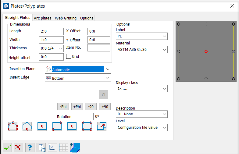
| Dimensions
|
- Length - Sets
the plate length for rectangular insertions.
- Width - Sets
the plate width for rectangular insertions.
- Thickness -
Selects the plate thickness from the drop-down list.
Tip: To edit or add available plate
thicknesses, click
 . The file
pro_st3d.ptt is opened in the default
text editor which you can use to edit the file.
Tip: Alternatively, to overwrite any
values, you can select the
Allow user input for Plate Thickness
option on the Options dialog
Straight Plates tab. Otherwise, only
values from this list may be selected.
- Height
offset - Sets the height of the plate above the current UCS.
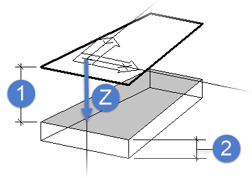
1)
Insertion height, 2) Plate thickness, Z) negative direction
- X-Offset - Sets
an offset in the X direction of the plate relative to the selected insertion
position. You can either enter this value or define the insertion point by
means of the data points.
- Y-Offset - Sets
an offset in the Y direction of the plate relative to the selected insertion
position. You can either enter this value or define the insertion point by
means of the data points.
- Item
No. - Specifies an item number.
- Grid - When on,
an additional grid is visible at the upper side that can be set. By this way
you can show that it isn’t a plate but a component part such as e.g.
gridirons. In the settings/plate, you can enter a reduction of weight in
percent for this case.
|
| Insertion Plane
|
Sets the user coordinate system to be used for
insertion.
- Automatic -
Inserts the place according the current settings.
- Current
ACS - Inserts the plate using the active ACS.
- Object
ECS - Inserts the plate by selecting a multi segment line element.
The plate is situated in the plane of the selected multi segment line.
- User-defined
plane - Inserts the plate on a UCS plane defined by two data
points.
|
| Insert Edge
|
Sets the vertical insertion position of the plate
relative to the current UCS or ECS system, depending on the selected option.
They are:
|
| Options
|
- Label - Assigns
a name for your plate from an editable file. The content of this file is
displayed in this list. Click
 to open
Pro_St3d.pdc. In addition to the name, you
can define a weight as well which is indicated with plain text. After selection
of a name, the material is directly set as well. to open
Pro_St3d.pdc. In addition to the name, you
can define a weight as well which is indicated with plain text. After selection
of a name, the material is directly set as well.
- Material -
Lists all available materials.
- Part
Family - If part families are defined, you can set them here. The
selection of part family can influence the colour of the component part.
- Detail
Style - If detailing styles are defined, you can determine them
here.
- Display
Class - If display classes are defined, you can determine them
here.
- Area
Class - If area classes are defined, you can determine them here.
- Description -
If general part descriptions are defined, you can determine them here. The
selection of the description can influence the colour and the layer.
- level - Here, you can specify on
which layer the plates have to be stored.
|
| Preview
|
Displays the selected plate in a plan view.
Insertion points are shown as well. Select one of these points to insert the
plate at this insertion point.
|
 By points By points
|
Inserts a plate by entering data points to form a
polygonal shape. This polygon is used to form a poly-plate after the dialog
closes. Construction lines or similar elements are not necessary. Make sure
that the polygon edges do not overlap.
|
 By shape By shape
|
Inserts a plate by selecting an existing element to
be the base of the plate. The selected element can be a polygon, a circle or an
arc. As with the insert by points method, there can be no overlapping edges.
However, the element does not have to be a closed shape. If an open shape is
selected, the tool closes the shape with a straight edge.
Note: Plates can alternatively be created on the
current UCS or on the selected element's ECS.
|
 Rectangular by insertion point Rectangular by insertion point
|
Inserts a rectangular plate using the
Length and
Width dimensions defined here at the
selected insertion point.
Note: The shape of
polygonal plates can be modified, but rectangular plates always remain
rectangular unless you change their status using Change Properties.
|
 Rectangular by diagonal points Rectangular by diagonal points
|
Inserts a rectangular plate based on a diagonal. The
alignment of the X and Y direction is specified by the current UCS.
|
 Rectangular on line Rectangular on line
|
Inserts a plate by selecting a line or line segment.
The length of the line determines the plate length.
Width and
Thickness are defined here. After insertion,
you can adjust the position, rotation and the insertion point with the controls
on the dialog. Rotation can either be modified in 90° increments or by user
defined increments. The plate is rotated about the insertion line.
- -Phi – Rotates
the plate in a negative direction using the
Rotation angle entered here.
- +Phi – Rotates
the plate in a positive direction using the
Rotation angle entered here.
- -90 – Rotates
the plate in a negative direction by 90°.
- +90 – Rotates
the plate in a positive direction by 90°.
|
| Rotation
|
Sets the value used for rotation by either the
+Phi or
- Phi options.
|
 By four points By four points
|
Inserts a plate by entering of four points. The
points do not need to be on the current UCS. The first three points define the
insertion plane. The order is: bottom left; bottom right, top left, top right.
|
 Transform flat to plate Transform flat to plate
|
Transforms a flat
ProStructures element into a
polyplate. Settings made here are applied to the new plate.
|
 Accept current Accept current
|
After insertion, plates are still connected to the
dialog. Modifications are still possible. Click to interrupt this connection,
thus preventing further modifications (via this dialog) to already inserted
plates.
|