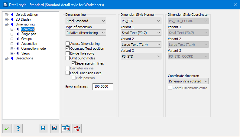
| Dimension Line Standard
|
Here, you define the fundamental method of
automatic component part dimensioning by selecting one of the standards.
- Steel Standard
– Standard dimensioning of
ProStructures; however, only
Steel component parts will be evaluated.
- Steel US –
Additional information is added to dimensioning chains and details as common in
the USA. Only
Steel component parts will be evaluated
- Concrete
Standard – Standard dimensioning of
ProStructures; however, only Concrete
component parts will be evaluated.
- Steel + Concrete
Standard – Standard dimensioning of
ProStructures; however, all
component parts will be evaluated.
- Steel + Concrete
US – Additional information is added to dimensioning chains and
details as common in the USA. All component parts will be evaluated.
Note: As far as the
difference of US-dimensioning to standard default settings is concerned, please
refer to a separate section of this chapter for more detailed information.
|
| Type of Dimension
|
Here, you select the kind of distance measuring
between the different dimensioning points.
- Relative –
customary relative dimension chains are attached.
- Coordinates –
dimensioning chains are attached with continuous dimensioning to a fixed
reference point.
- Mixed –
relative dimension chains and – at the same time here included – the
corresponding coordinate dimensions are attached.
However, you have the option to exclude certain
freely selectable dimensioning chains from coordinate dimensioning.
|
| Associative Dimensioning
|
The dimensioning is created as really associative
dimensioning without text overwriting as far as possible. In case of manual
manipulations dimensioning is automatically adapted to the measured values.
|
| Optimized text Position
|
The program will position the dimensioning texts in
a better way according to the settings on the page ‘Optimization’. Optimization
can be switched off later if you want to displace the dimensions manually
according to another method or if you do not expect overlaps. You will then
obtain the dimensions on the position where
AutoCAD®
would
place them automatically.
|
| Divide Hole Rows
|
At hole dimensioning each individual hole diameter
gets its own dimension chain. The dimensioned hole diameter then is indicated
on the dimension line.
|
| Omit Punch Holes
|
Excludes weld mark dimensioning, as apposed to
Separate dimension lines, where additional
dimension line is used for weld marks.
|
| Diameter on Line
|
At hole dimensioning the hole diameter is indicated
on the dimension construction line if 'Divide Hole Rows'
has been checked.
|
| Label Dimension Lines
|
Adds labels to separate dimension lines indicating
destination. The things located by dimension chain are written as additional
text to the end of dimension line. The text depends on the settings for
dimensioning groups.
|
| Hole Position
|
If this field has been checked, a text is added to
inform about the assignment to position (top/bottom) for dimension chains of
drill holes which are divided according to depth position (Z-direction).
|
| Weld Cracks Extra
|
Small welding cracks will be assigned their own
dimensioning line. This is a minor option if ‘Divide Hole Rows’ has been
selected because here a distinction is made between diameters anyway.
|
| Bevel Reference
|
Angle dimensions can be indicated as gradient instead
of as angle. Here you enter the reference value for calculating the gradient.
|
| Dimensioning Style —Normal / —Coordinate
|
Here you can select the dimensioning style to be used
for the dimensioning in question. This style is going to control all properties
such as text color, text size, etc. For radii and angles the corresponding
subordinate style of the dimensioning style can additionally be used.
|
| Variant 1 / 2 / 3
|
Here, you can indicate three alternative styles to
be assigned as style variant to different dimension chains.
If you have selected the entry
Small Text (Auto Smaller), a copy with
smaller text sizes (factor 0.7) is generated from the basic style. If you have
selected the entry "Large Text (Auto Larger), a copy
with larger text sizes (factor 1.4) is generated from the basic style. Style
variants allow you e.g. to emphasize overall dimensions or to use smaller texts
when space is limited. Please also refer to section Style Variants in this
chapter.
|
| Coordinate Dimensions
|
Here you select the kind of coordinates.
- Dimension Line
Rotated – The coordinates are attached
beside the second construction line as a measure which is rotated by 90°. Some
parameters of dimensioning style are modified at this occasion.
- Like Dimensioning
Style – The coordinates are attached in the indicated dimensioning
style without any modifications.
-
AutoCAD
Coordinate Dimension – The coordinates
are attached in the indicated dimensioning style without any modifications as
real
AutoCAD
coordinates.
|
| Coordinate Dimensions Extra
|
Any possibly existing coordinates dimensioning chains
are summed up to one dimensioning chain per dimensioning side and attached
completely outside. Mixed dimensioning chains are transformed into standard
relative dimensioning chains.
|