Detail Style-Dimensioning - Single Parts-Reference Points tab
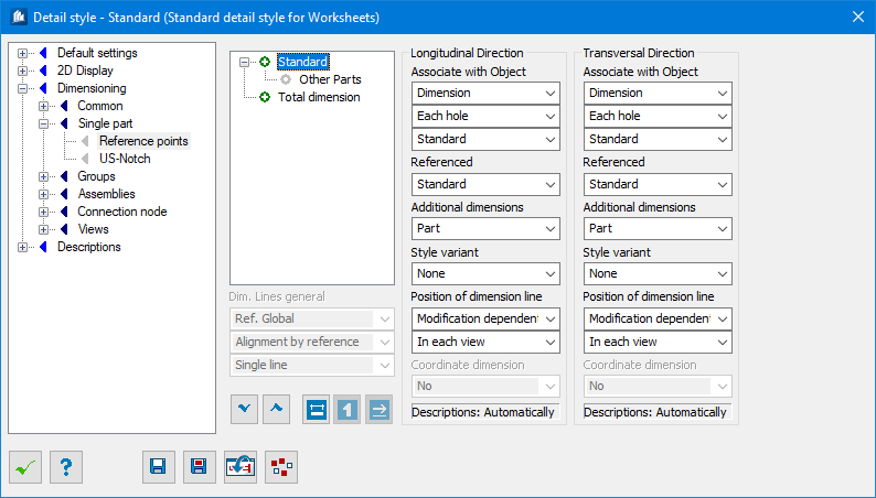
Here, you select the treatments for which you want to attach single part dimensions in the detail and determine the dimension points as well as the position of dimension chains.
List of Dimensioning Groups
The following dimensioning groups can be added:| Modifications | |
| Outer Contour | Running of outer contour |
| Inner Contour | Running of inner contours (inner sections) |
| Drill holes as plan view | Drill holes which can be seen as visible or invisible hole circle |
| Drill holes as view | Drill holes which can be seen as intersection or hidden solid |
| Angle of intersection | Diagonal edges of components in the outer contour |
| Radius center | Centers of radii in outer and inner contour |
| Special Dimensions | |
| Reference Points | Dimensions of the position of the two reference points |
| US-Cope | American lengths and depths for copes at the end |
| Local reference planes | Position of reference planes (connection profile) when reference is set to the connection profile |
| Part Groups | |
| Fittings | Dimensions of the position of integrated fitting elements at concrete panels |
| Outer Contour / Inner Contour | |
| Standard | Normal dimensioning over the outer contour in dimensioning direction |
| Individual outside | Each edge is individually dimensioned in its alignment; placing outside |
| Individual inside | Each edge is individually dimensioned in its alignment; placing inside |
| Standard + Individual outside | Combination of Standard and Individual edges outside |
| Standard + Individual inside | Combination of Standard and Individual edges inside |
| Min / Max | Min/Max contour dimensioning (see ‘outer contour’) |
| Standard + Min / Max | Combination of Standard and Min/Max (see ‘outer contour’) |
| Drill Holes | |
| Common | Normal dimensioning over the drill holes in dimensioning direction |
| Reference to Edge | The holes are dimensioned to the next edge of the component part |
| Hole Groups | Groups of identical holes are dimensioned once in transversal direction |
| Common + Edges | Combination of standard dimensioning and reference to edge |
| Hole Groups + Edges | Combination of hole group dimensioning and reference to edge |
| Angle of Intersection | |
| Angle towards Vertical Line | The angle towards the imaginary vertical reference line (opening angle) |
| Angle towards Horizontal Line | The angle towards the horizontal component direction (material angle) |
| Bevel Symbol | Bevel symbol (triangle) of the edge related to reference length or -height |
Examples
The following examples show you the results of the different extended forms of dimensioning for single parts:
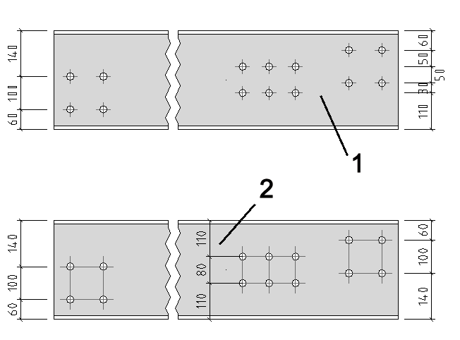
Reference to Edge (1) and Individual Edges (2)
The holes are related perpendicularly to the following edge of the plate; the edges of a plate are dimensioned individually.
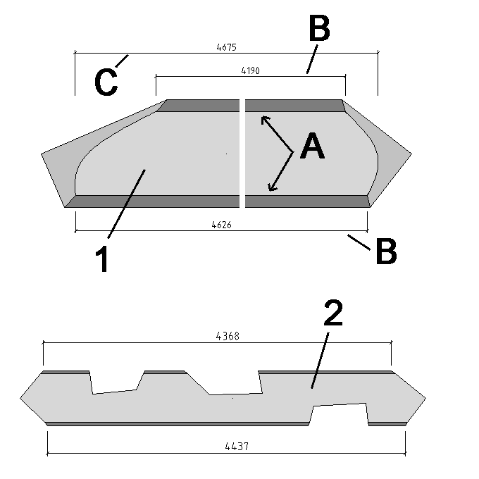
At a hollow shape, the maximum extension of the interior wall (A) is dimensioned with the dimension chain (C) and the minimum extension is dimensioned with the dimension chains (B). Possible cut-outs haven’t any influence.
At a standard shape the longest exterior area on the upper and lower side is dimensioned with a single measure at a time despite the cut-outs.
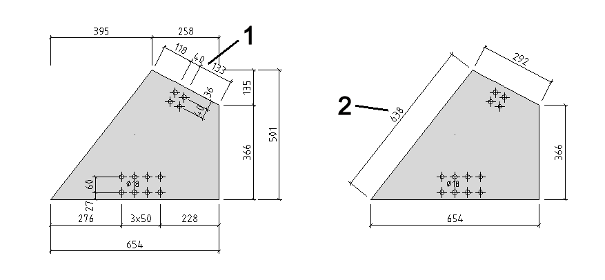
Reference to Edge Inside/Outside
The outer contour is dimensioned with the combination of standard dimensioning and individual edges inside (only the diagonal edges are dimensioned with individual dimensions). The inner contour is dimensioned with the combination of standard dimensioning and individual edges outside (all edges are always dimensioned with individual dimensions).
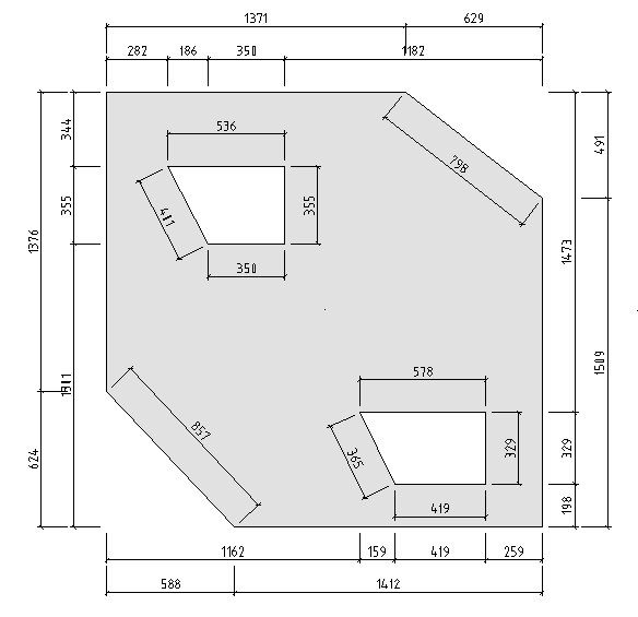
The drill holes are dimensioned in a common dimension chain at the edge.
Inner hole groups are dimensioned separately in their own dimension chains.