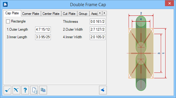
Double Frame Cap
 Used to parametrically create
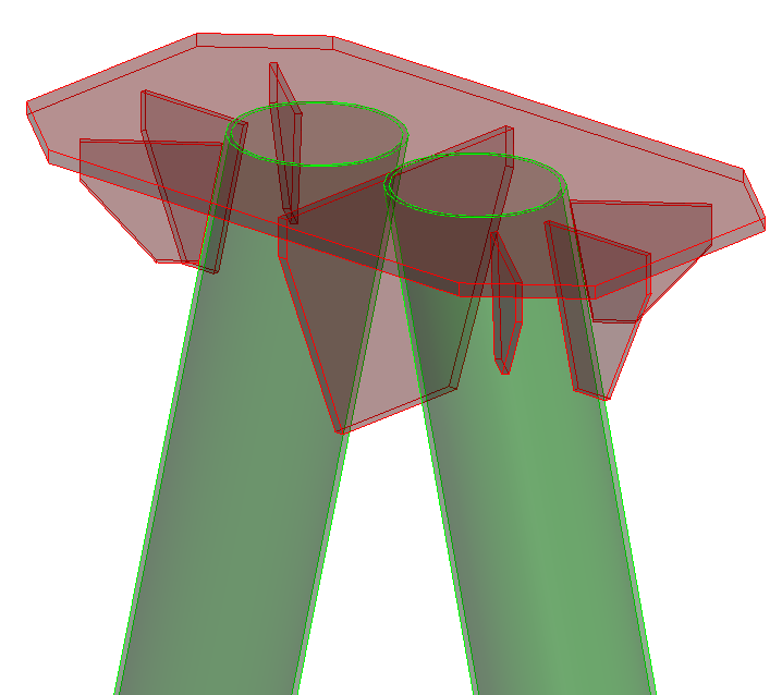
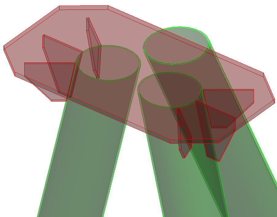
stiffened cap plates, commonly used in electrical substations. Double frame
caps can be placed on Symmetric A Frames or Trestles.
Used to parametrically create
stiffened cap plates, commonly used in electrical substations. Double frame
caps can be placed on Symmetric A Frames or Trestles.
Cap Plate tab
Used to define the cap plate geometry.
| Setting | Description |
|---|---|
| Rectangle | When on, the cap plate corners are not chamfered. |
| Thickness | Sets the thickness of the plate. |
| Outer Length / Width | Sets the outside dimensions of the plate. Denoted with 1 and 2 in the diagram. |
| Inner Length / Width | Sets the dimensions between the chamfers of the plate. Denoted with 3 and 4 in the diagram. |
Corner Plate tab
Used to specify the inclusion of corner stiffener plates and their geometry. Illustrated with yellow color in the diagram.
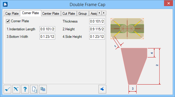
| Setting | Description |
|---|---|
| Center Plate | When on, the center stiffener plates are included with the frame cap. |
| Thickness | Sets the thickness of the plate. |
| Indentation Length | Sets an offset distance from the top cap plate edge to the center stiffener plate(s). Denoted with 1 in the diagram. |
| Height | Sets the overall height of the plate. Denoted with 2 in the diagram. |
| Bottom Width | Sets the width of the plate at the bottom. Denoted with 3 in the diagram. |
| Side Height | Sets the height of the plate where it is attached to the frame. Denoted with 4 in the diagram. |
Center Plate tab
Used to specify the inclusion of center stiffener plates and their geometry. Illustrated with yellow color in the diagram.
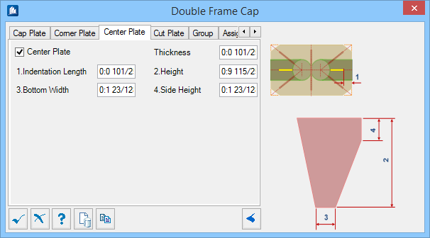
| Setting | Description |
|---|---|
| Center Plate | When on, the center stiffener plates are included with the frame cap. |
| Thickness | Sets the thickness of the plate. |
| Indentation Length | Sets an offset distance from the top cap plate edge to the center stiffener plate. Denoted with 1 in the diagram. |
| Height | Sets the overall height of the plate. Denoted with 2 in the diagram. |
| Bottom Width | Sets the width of the plate at the bottom. Denoted with 3 in the diagram. |
| Side Height | Sets the height of the plate where it is attached to the frame. Denoted with 4 in the diagram. |
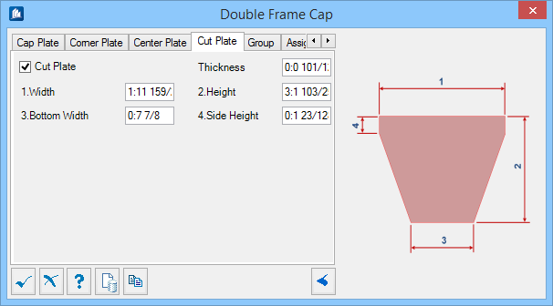
Cut Plate tab
Used to specify the inclusion of cut stiffener plates and their geometry.
| Setting | Description |
|---|---|
| Cut Plate | When on, the cut plate is included with the frame cap. |
| Thickness | Sets the thickness of the plate. |
| Width | Sets the width of the plate at the top where it is attached to the cap plate. Denoted with 1 in the diagram. |
| Height | Sets the overall height of the plate. Denoted with 2 in the diagram. |
| Bottom Width | Sets the width of the plate at the bottom. Denoted with 3 in the diagram. |
| Side Height | Sets the height of the plate on both sides. Denoted with 4 in the diagram. |
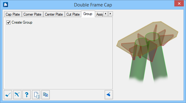
Group tab
Used to create a new ProStructures group with the double frame cap objects.
| Setting | Description |
|---|---|
| Create Group | When on, you can select additional shapes. Separate double frame caps are created. |
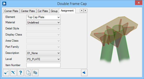
Assignment tab
Used to assign elements in the connection to a material, display class, area class, part family, level, etc.
Dialog Controls
| Setting | Description |
|---|---|
 OK OK
|
Closes the dialog and save your changes. |
 Cancel Cancel
|
Closes the dialog without saving changes. |
 Help Help
|
Opens online help. |
 Template Template
|
Saves and retrieve (Using Templates) settings to be used on other projects. |
 Clone Clone
|
Shifts focus to the geometry, allowing cloning the current structural object (stair, frame, truss, etc.) properties to match one or more objects selected in the view. |
  Show /Hide
Preview Show /Hide
Preview
|
Opens or closes, respectively, a flyout panel to display an illustration based on the tool. |