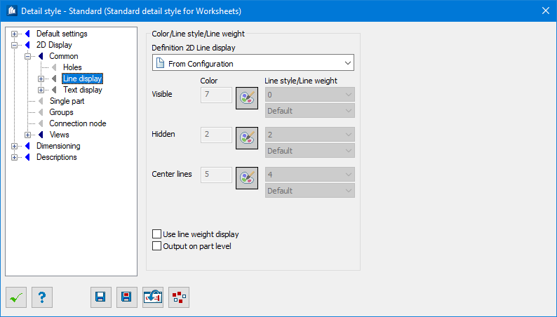
| Definition 2D line display
|
Used to select the source from which the definition
of the line type representation is taken for the three object line types
‘Visible’, ‘Hidden’ and ‘Center line’. This determines which line type and line
color are used for an object in 2D mode.
- From
configuration – The definitions are taken from the
ProStructures configuration file.
- From
description file – The definitions are taken from a separate instruction file.
This file contains descriptions of parts that can also be used for dimensioning
and representations in overviews.
- From
part family – The definitions are taken from the part family under which the
relevant part is classified.
- From
detail style – The definition is taken from the settings on this page. Enables
the color and line style/weight settings below.
|
| Colour
|
Enter the number for color to be used for lines. The
appropriate color code should be used.
|
 Select Color Select Color
|
Sets the color to the active Colors element from the
Color selection dialog.
|
| Line style / Line weight
|
Enter the type of line to be used for
Visible,
Hidden, and
Center Lines.
|
| Use line weight display
|
When checked, uses the line weight for displaying
the lines.
|
| Output on part layer
|
When checked, the lines are shown on the same layer
name as the original part in the 3D model. When unchecked, they are shown on
the layers for visible or invisible lines.
|