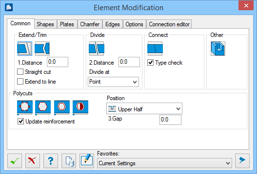
| Extend/Trim
|
Used to extend or trim shapes with intersecting
shapes or lines.
 – Allows complete shapes to be
cut or extended at boundaries, similar to the Stretch command for the
stretching and cutting lines. – Allows complete shapes to be
cut or extended at boundaries, similar to the Stretch command for the
stretching and cutting lines.
You must select the shape at the end to be cut
and then select the cutting line. The boundary is completely formed by a
construction line. An imaginary plane passing through the construction line,
normal to the active coordinate system is the cutting plane used. If the plane
is slanted, the modified shape has a slanted plane as well. By using this
function, shapes that are too long or too short can be adapted to fit after
their insertion. When you enter a value in the
Distance field of the main dialog, the
shape is trimmed (shortened) by this value after it is cut. The distance refers
to a vertical distance between shape and cut plane.
The shape is cut at an imaginary plane, the
line being oriented vertically to the active coordinate system plane. Working
in a
"top" oriented view simplifies your work,
since the shape is cut at the line. If the shape can intersect with the line
(consider the line to have infinite length), the shape is cut. To extend the
shape, hold down the <Alt> key while clicking the end to be extended.
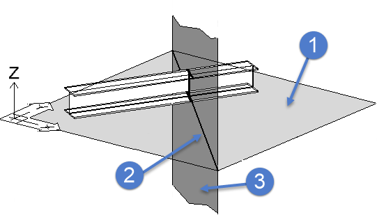
1) UCS
plane, 2) Cut line, 3) Imaginary cut plane
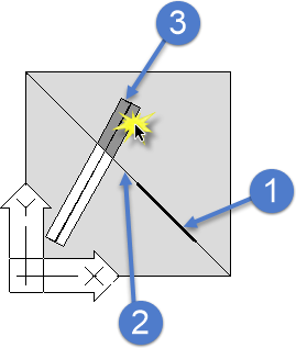
1) Cut
line, 2) Cut plane, 3) Removed where selected
 – Allows the shape to be cut or
extended at another shape. When the shape is cut, the shorter section is always
cut off. Click the shape to be cut and then the shape along which this shape is
to be cut. – Allows the shape to be cut or
extended at another shape. When the shape is cut, the shorter section is always
cut off. Click the shape to be cut and then the shape along which this shape is
to be cut.

The
plane intersected by the centerline (or the extended centerline) of the shape
to be cut is the cut plane (top, middle). If the centerline does not meet any
surface, no cut can be made (bottom).
Note: A logical link is created between the parts
if this option is applied. If one part is modified, the cut is automatically
updated.
- Distance –
Trims the cut shape back by the entered value from the cut plane.
- Straight
cut – Trims the cut shape perpendicular to its centerline.
- Extend to
line – Trims the cut shape exactly along the the cut plane created
by another shape's intersecting plane or by a line.
|
| Divide
|
Used to divide a shape at a cutting line into two
shapes. A single shape, a plate or several elements can be divided into two
independent elements.
-
 – When using
this function, start by selecting the shape to be divided. Then the cutting
line. When you enter a value for
Distance, both new ends are shortened by
this value. – When using
this function, start by selecting the shape to be divided. Then the cutting
line. When you enter a value for
Distance, both new ends are shortened by
this value.
Note: Depending
on the setting, you can divide several elements at the same time. However, the
distance refers to a vertical distance between shape and cutting line.
- Distance – The
two new shapes are shortened by this value at the cutting line. The overall gap
is double the entered value.
- Divide
at – Used to select how the cutting plane is generated.
- Point – The
cutting line is created with a single point, which is perpendicular to the
centerlines.
- Line – The
cutting line is created with a line. If the line is slanted, the shapes are
divided accordingly.
- Plane – The
cutting plane is created by entering three points. The shape is divided along
this plane.
Note: The information for the parts lists is
identical for both parts with that of the initial shape, except for the length.
|
| Connect
|
Used to join two shapes into one shape. The shapes
must exactly aligned (coplanar and have a coincident point) to use this option.
 - When using this function,
select the two shapes to be combined. If they are not in alignment, the
function is aborted. If they are aligned correctly the two shapes become one
shape. - When using this function,
select the two shapes to be combined. If they are not in alignment, the
function is aborted. If they are aligned correctly the two shapes become one
shape.
Note: The
information for the parts lists of the new shape is identical with that of the
first selected shape, except for the length.
- Type
check - When on, the two shapes must be of the same type to be
joined.
Tip: Press and hold the <ALT>
key to prevent the shape and position from being checked. Then, you can combine
any shape with any shape.
|
 Other Other
|
Opens the Notch dialog which is used to insert
simple geometrical shapes of outlets and countersunk parts into shapes.
|
| Polycuts
|
Used to cut out shapes along any freely drawn
contour (poly-line). You can create notches that can not be made with Notch
functionality. You can also subtract one shape from another to create
penetrations, to create slotted tubes, penetrated handrail posts or other
combinations.
Note: If you enter a value in the
Gap input field of the main dialog, the
cut-out is regularly extended to all directions by the indicated value to gain
some space for inaccuracies of production.
Note: In any case, the cutting polygon is extended to
the top and to the bottom in the coordinate system's Z-plane. Therefore, ensure
your UCS has been selected accordingly. In case of a direct use of this
function via key-in, the current settings of the main dialog apply.
 – Use this option if you do not
have a contour element to select. Rather, enter the data points to create the
contour. Make sure the contour is a closed polygon. – Use this option if you do not
have a contour element to select. Rather, enter the data points to create the
contour. Make sure the contour is a closed polygon.
 – Use this option if you have a
contour element to select. – Use this option if you have a
contour element to select.
 – Use this option if you want to
subtract the contour of another solid from the selected object (penetration or
solid to be subtracted). – Use this option if you want to
subtract the contour of another solid from the selected object (penetration or
solid to be subtracted).
 – Use this option for straight, hollow shapes only.
The internal portion of the subtraction between the hollow shapes and other
straight shapes or plates is retained. – Use this option for straight, hollow shapes only.
The internal portion of the subtraction between the hollow shapes and other
straight shapes or plates is retained.
 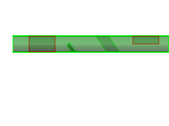
Before
(left) and after (right) using an inverse boolean subtraction on a hollow
shape
- Update
reinforcement – When on, reinforcements are updated accordingly.
- Position – Sets
the option on what height the cut be performed:
- Complete – When
selected, the cut travels through the entire cut shape.
- Upper
half – When selected, the cut travels through only the upper
portion of the cut shape.
- Lower
half – When selected, the cut travels through only the lower
portion of the cut shape.
- Gap – Used to
specify a gap by which the cut contour is increased before the subtraction.
|