| Stair runs
|
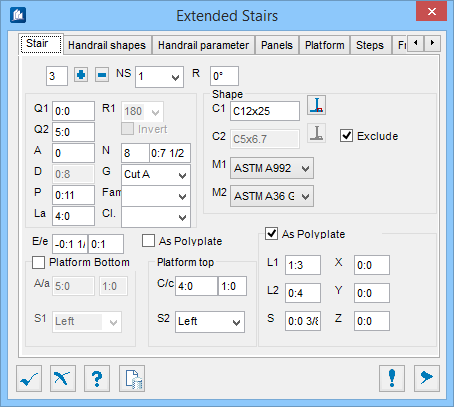
Settings used to define the runs, level and rotation
of the staircase.
- [
] (the first field) – displays the total number of stair runs in
this stair. Indicates the amount of staircase runs to be inserted into the
staircase element.
- [+] – Adds a
stair run to the stair.
- [-] – Removes
the top-most stair run from the stair.
- NS – Select the
run number to display and edit the stair run parameters. For multiple levels,
allows selecting current level being modified.
- R – Sets the
rotation angle of the entire staircase from its initial direction, taken
counter-clockwise from the X-axis defined when the stair was inserted. An
angular value should be entered. Negative values may be used.
|
| Stair specifications
|
Settings used to define the orientation and spacings
of the staircase elements.
|
| Shape
|
Settings used to define the stair shape and
material.
- C1 – Cheek
(stringer) shape. Determines the basic shape for the stringer elements used in
the staircase.
 (Select Shape tool) – Opens the
Shape Selection dialog, used to select a catalog shape from a list of standard
shapes and sizes. (Select Shape tool) – Opens the
Shape Selection dialog, used to select a catalog shape from a list of standard
shapes and sizes.
Note: Changing this value affect the entire staircase.
- C2 – Cheek
shape low (platform support member). Adjusts the stringers shapes supporting
the platforms.
- (Select Shape tool) – Opens the
Shape Selection dialog, used to select a catalog shape from a list of standard
shapes and sizes.
- Exclude – Cheek
shape low (platform support member). When checked, enables the
C2 stringer shapes for the entire
staircase.
This option works with values (A/a,
C/c,
S1 and
S2) located in the ‘Platform
bottom’ and
Platform top’ sections located near the
bottom left of this dialog window.
- M1 – Sets the
material associated with the shape provided in
C1.
- M2 – Sets the
material associated with the grating plates provided in
C2.
|
| E/e
|
Distance between the platform and the top-of-steel
of the platform support member. Sets the horizontal and vertical
(straight/oblique cheek shape) offsets of the plates (grating) and steps. The
plates can be adjusted from the original placement point horizontally,
lengthening or shortening them towards or away from the stairs. The step
locations in relation to the stringers move vertically from the ToS of the
stringer.
|
| As Polyplate
|
When checked, sets to model plate steel objects
using polyplate CAD objects. Meaning, the start plate will be placed as a
polyplate rather than being placed as a shape (flat bar).
|
| Platform bottom
|
When checked, a platform is paced at the bottom of
the staircase for the selected level. Used to include a platform at the bottom
of the selected stair run. Moves the current staircase (NS) and ones above it
from its current position.
Disabled for the first stair run.
- A/a – These two
fields are:
- A - Indicates
the overall length of the platform, taken from the face of the lower stringer
knee. Changing or modifying this value will also change the staircase location,
and
- a - Indicates
the length of the original stringer size, ‘C1’ shape in this
support member that will remain under the platform. Effective only when the
Exclude, next to
C2 is unchecked.
The remainder of the length will use the
‘C2’ shape.
Tip: If the
Exclude option is set for C2, then the
C1 shape is the full length of A.
- S1 – When two
different members are being used (the
Platform bottom is enabled and the support
members are set using the
A/a), then you can also decide from which
side(s) is affected by these settings.
Selects the side of the bottom platform which will
not have a handrail (and panel, if set):
- NO - Neither
side has an handrail for this platform.
- Right - The
right side is open.
- Left - The left
side is open.
- L/R - Both sides
of the platform are enclosed with a handrail.
|
| Platform top
|
Set this option to include a platform at the top of
the selected stair run.
- C/c – These two
fields are:
- C - Determines
the overall length of the top platform taken from the face of the lower
stringer knee, and
- c - Determines
the length of the original stringer size, 'C1' that will
remain under the top platform C1 shape in this support member. Effective only
when the
Exclude, next to
C2 is checked.
The remainder of the length will use the
‘C2’ shape.
- S2 – When two
different members are being used (the
C/c set in
Platform top), then you can also decide from
which side(s) is affected by these settings. It will also affect the handrails
on the topmost platform and allow you to decide which way the staircase should
be exited from.
- NO - Neither
side has an handrail for this platform.
- Right - The
right side is open.
- Left - The left
side is open.
- L/R - Both sides
of the platform are enclosed with a handrail.
It does not affect the intermediate platform handrails, (
L in Handrail Parameters tab) .
|
| Start plate
|
When checked, includes a base plate at the bottom of
the first stair run stringer foot that can be adjusted using the below options.
Enabled only if the ‘Platform bottom’ is unchecked.
- L1 – Sets the
length of the start plate parallel to the bottom stringers.
- L2 – Sets the
width of the start plate, i.e. the -the length perpendicular to the bottom
stringers.
- S – Sets the
thickness of the start plate.
- X/Y/Z
– Coordinate offsets from the geometric center of
the end of the stringer knee to the centroid of the start plate.
- X – Shifts the
plate from its insertion point either inwards or outwards depending on the
value entered.
- Y – Shifts the
plate from its insertion point either forwards or backwards depending on the
value entered.
- Z – Shifts the
plate from its insertion point either upwards or downwards depending on the
value entered.
Note: The stringer will try to move with the plate when
using this option.
|