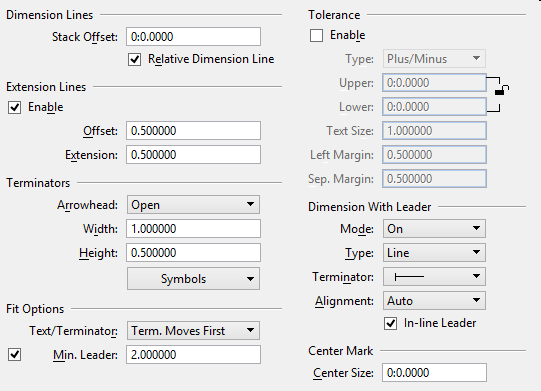
| Dimension Lines
|
Consists of controls that affect the general
appearance of dimension lines.
- Stack Offset -
Sets the space, in working units, between
dimension lines if dimensions are stacked.
If set to 0.0 (the default), a reasonable value
based on text size and orientation is computed. Set Stack Offset to a value
other than 0 only if you need constant spacing between dimension lines.
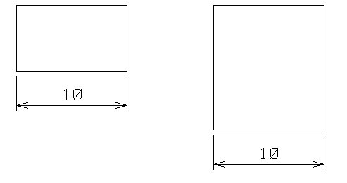
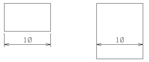
- Relative Dimension
Line -
If on, the dimension line moves relative to the
length of the first extension line so that when the geometry moves, the
extension length remains constant.
If off and the geometry moves, the dimension
line location stays constant and the length of the extension changes.
|
| Extension Lines
|
Consists of controls that affect the placement of
extension lines (also called witness lines or projection lines).
- Enable -
If on, extension lines are placed. If off,
extension lines are not placed.
When you place interior dimensions, it is often
useful to suppress extension line placement to avoid an intersecting extension
line.
Key-in:
DIMENSION EXTENSION [ON | OFF |
TOGGLE]
- Offset -
The distance, in text height units, between the
start of the extension line and the element.
A negative value forces the length of the
extension line from the dimension line to the end of the extension line. This
is relative to the text height. For example, if the text height is 0:6, an
offset value of -5 produces extension lines with a length of 2'-6".
- Extension -
Sets the distance, in text height units, that
the extension line extends beyond the dimension line.
|
| Terminators
|
Consists of controls that set the appearance and
geometry of the default dimension terminators.
Geometry measurements are based on the text size.
For example, if the height is set at 0.25 and the width is set at 0.5, then the
terminator size would be 0.25 of the text height and 0.5 of the text width.
When Uniform Cell Scale is turned on, the terminator size would be a scale
factor of 0.25 for a shared cell.
- Arrowhead -
Controls the appearance of the default arrowhead
terminator — Open, Closed, or Filled.
Under the Symbols menu, the Arrow control can
be used to specify an alternate arrowhead.
- Width -
Sets the terminator width, in text height
units.
When Uniform Cell Scale is on, the Width value
uniformly scales the cell terminator width and height, in text height units.
- Height -
Sets the terminator height, in text height
units.
- Symbols -
Consists of controls that are used to specify
alternate symbols (characters from symbol fonts or cells) for each of the
default dimension terminators.
Font 102 is the symbol font in the font library
supplied with
ProStructures that contains
terminator symbols.
Various terminator types are associated with
particular dimensioning tools; some of the tool names even specify a terminator
type. See the
Advanced tab Tool Specific category for more information.
The active dimension settings can be set to
match those of a dimension element with the
Match All Element
Settings tool.
- Symbols: Arrow -
Specifies an alternate to the default
Arrowhead.
- Default —
Default arrowhead.
- Symbol —
Character and Font (by number) that you enter in the adjacent fields.
- Cell — Cell
name that you enter in the adjacent field.
When a dimension is placed, the specified cell
is placed as a shared cell, so its definition must exist in the design file.
- Symbols: Stroke -
Specifies an alternate to
ProStructures's default stroke
terminator symbol (choices are the same as for Arrow).
- Symbols: Origin -
Specifies an alternate to
ProStructures's default origin
terminator symbol (choices are the same as for Arrow).
- Symbols: Dot -
Specifies an alternate to
ProStructures's default dot
terminator symbol (choices are the same as for Arrow).
- Symbols: Note -
Specifies an alternate to
ProStructures's default Place
Note terminator symbol (choices are the same as for Arrow).
- Uniform Cell Scale -
Controls how cell terminator size is defined.
This control does not affect terminators defined with the Default or Symbol
setting.
If on, the Terminator Width value uniformly
scales both the width and height of cell terminators, in text height units. The
Terminator Height value is ignored.
For example, assume that the Terminator Width is
1.5 and the text Height (under the Text tab) is 2.0. When you place a dimension
that has a cell terminator, the terminator 's size is the cell definition size
multiplied by 3.0. Uniform Cell Scale is useful if you plan to save a DGN file
to DWG format, since the DWG format requires cell width and height to be
uniform.
If Uniform Cell Scale is off, the Terminator
Width value sets the terminator width in text height units. The Terminator
Height sets the terminator height.
This control is available only in DGN workmode.
It is controlled by the configuration variable
CAPABILITY_DIMENSION_CELLTERM_HEIGHT.
|
| Fit Options
|
Consists of controls that affect the general
appearance or placement of text and terminators.
- Text/Terminator -
Selects the minimum fit dependant on the text,
terminator or combination.
- Min. Leader -
Sets the space, in text width units, between
extension lines and dimension text.
Note: The Fit
Options only apply to angular and linear dimensions.
|
| Tolerance
|
Consists of controls that affect the generation of
dimensions with Tolerance.
- Enable -
If on, displays tolerances.
If off, does not display tolerances.
- Type -
Sets the format for the tolerance:

Tolerance types from top:
Plus/Minus; Plus/Minus if Upper and Lower limits are different; Limit
- Plus/Minus —
The dimension and the upper and lower limits are expressed as positive and
negative limits.
- Limit — The
dimension is expressed as the upper and lower limits.
- Upper -
Sets the upper tolerance limit, in working
units.
A positive limit in the upper tolerance and a
negative limit in the lower tolerance will produce a positive number for the
upper tolerance and a negative number in the lower tolerance when the dimension
is placed.
Key-in:
DIMENSION TOLERANCE UPPER
[MU:SU]
- Lower -
Sets the lower tolerance limit, in working
units.
Key-in:
DIMENSION TOLERANCE LOWER
[mu:su]
- Text Size -
Sets the tolerance text size, specified as a
multiple of the dimension text Height and Width.
Key-in:
DIMENSION TOLERANCE SCALE
[factor]
- Left Margin -
Sets the horizontal space, in text height
units, between tolerance text and dimension text.
- Sep. Margin -
Sets the vertical space, in text height units,
between tolerance values.
|
| Dimension With Leader
|
Consists of controls that affect the general
appearance of dimension leaders. You can modify the location of a dimension
value to something other than horizontal along the dimension line. You can also
modify how the dimension text visually identifies the dimension with which it
is associated.
- Mode -
- None (default)
— displays dimension with no leader.
- On — allows
display of a leader with dimensions.
- Automatic —
automatically places a leader with a line dependent on the Fit Option.
- Type -
Sets the type of leader line to display: None,
Line, Arc, or Bspline.
- Terminator -
Sets the type of terminator to display: none,
arrow, slash, empty ball, or filled ball.
- Alignment -
Sets the option for placing the leader are
Auto(matic), Left, or Right.
- In-line Leader -
If on, adds a horizontal line in front of the
dimension text.
Note: Dimension with a leader can be placed only when the
Location option is set to
Manual in the tool settings window of the
dimensioning tool.
|
| Center Size
|
Sets the size of the center mark in radial
dimensions. If set to 0, the center mark size is the active text height. If set
to a negative value, extension lines are added to the center mark.
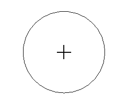 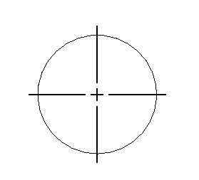
Left:
Center Mark with center size = 0.05 / Right: center size = -0.03 (negative
value shows extension lines)
Offset distance and length of extension lines can be set by
enabling
Extension Lines or can be dynamically
adjusted in the drawing when
Association is off.
Changes made to the Center Size value in the
Place Center Mark tool settings get
reflected here. You can save the changes or reset to previously saved value.
DIMENSION
CENTER
SIZE
[mu:su:pu]
|