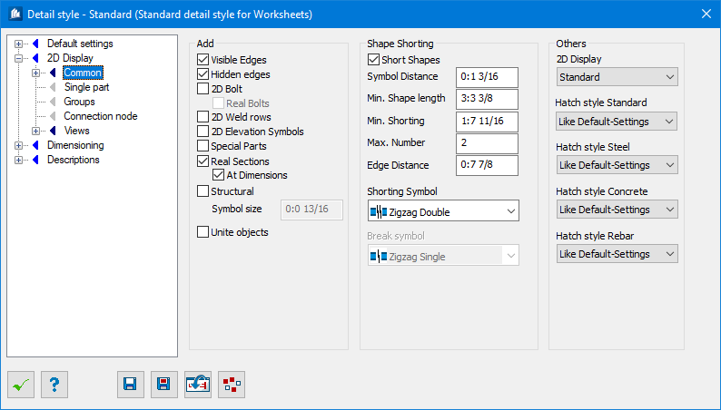
Detail Style - 2D-Display - Common tab
| Setting | Description |
|---|---|
| Visible Edges | All visible lines are displayed according to their line type. |
| Invisible Edges | The invisible lines are displayed according to their line type. |
| 2D-Bolts | The put in bolts are depicted by a bolt symbol. |
| Real Bolts | The bolts are depicted as real view with nut and bolt head. |
| 2D-Weld rows | The welding joints imported to the model are depicted as weld symbol. |
| 2D-Elevation symbols | The height indicators imported to the model are depicted. |
| Special Parts | Special parts inserted into the model are depicted. These may be any parts (such as e.g. blocks) containing ProSteel component part characteristics. |
| Real Sections | The shape cross-sections are depicted with their exact radii – otherwise, the simplified depiction in the form of straight lines is selected. |
| At Dimensioning | At dimensioning, all edges and radii of cross-section display are used. Otherwise, only the outside dimensions are depicted. |
| Bearing Bar Direction | A symbol for the bearing bar direction is attached (which corresponds to the lengthwise direction of the grid) if it is a matter of plates having a grid. |
| Symbol Size | Here, you enter the size of the symbol, which is used for the direction of the plate grid. |
| Unite objects | For solid display, the objects will be displayed as united. |
| Short Shapes | Shapes are compressed in areas without detailing and a shortening symbol is attached. Whether a shape can be shortened depends on its detailing processes and on the limits specified by you hereafter. |
| Symbol Distance | The gab in the shape or the distance between the lines if a shortening symbol with two lines is used. |
| Min. Shape | Length Shortenings are to be attached starting at this length. You can use your page optimally by displaying the shapes as long as possible. |
| Min. Shortening | The shape has to be shortened by at least this value to even activate any shortening. |
| Max. Number | The maximum number of shortenings inserted into the shape. |
| Distance Edge | Shortenings cannot start at the edge or margin area but can only start this indicated distance from the edge. This prevents shortening a shape without detailing too much. |
| Shortening Symbol | Here, you select the symbol, which has to be
inserted into the shape at shortening position.
|
| Break Symbol | Here, you select the symbol, which has to be inserted at the break edge of the completely cut-off shape end. Please also refer to ‘Shortening Symbol’. |
| 2D Display | Here you can select the processes used to create plans from steel and concrete elements during overviews. The opposing elements will then usually be displayed in a less true-to-life manner. |
| Hatch pattern | Used to enter the template setting out the pattern
or type of line used for hatching cut objects.
You can create new templates using the function for manual 2D cutting (Dialog controls), where only the templates for hatching are used. |
| Hatch size | Allows a scaling to be entered for the hatching pattern selected. This scaling affects the line spacing of the hatching. |