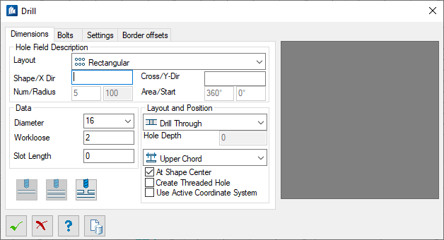
| Layout
|
Selects the general form of the drill hole field.
- Single – Allows
the position of each hole to be determined individually.
- Radial –
Arranges the drill holes in a complete or partial circle around the insertion
point. Additional input fields are displayed allowing you to define round drill
hole fields.
- Rectangular –
Arranges the drill holes in a rectangular pattern around the insertion point
forming rows and columns. In general, drill hole fields are described as
follows:
Number1*Pitch1, Intermediate Pitch1, Number2*Pitch2, Intermediate Pitch2,...
|
| Shape/X Dir
|
Enabled for the
Rectangular hole layout. Defines the drill
hole field pattern in the X-direction of the UCS.
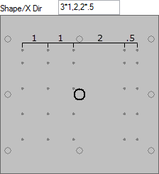
Example
3*1,2,2*.5:
3*1 defines first three columns of holes
with X spacing equal to 1,
2 defines the intermediate X distance
between the 3rd and 4th column of holes, and
2*.5 defines the last two columns of holes
with X spacing equal to .5
|
| Cross/Y Dir
|
Enabled for the
Rectangular hole layout. Defines the drill
hole field pattern in the Y-direction of the UCS.
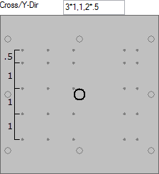
Example
3*1,1,2*.5:
3*1 defines first three rows of holes
with Y spacing equal to 1,
1 defines the intermediate Y distance
between the 3rd and 4th row of holes, and
2*.5 defines the last two rows of holes
with X spacing equal to .5
|
| Num/Radius
|
Two value fields are enabled for the
Radial hole layout.
- Num field -
Defines the number of drill holes.
- Radius field -
Defines the radius of the circle where the drill holes are arranged around the
insertion point.
|
| Area/Start
|
Two value fields are enabled for the
Radial hole layout.
- Area field -
Defines the angular range in which the drill holes are distributed.
- Start field -
Defines the start angle from which the drill holes are distributed.
|
| Diameter
|
Specifies the bolt diameter. You can select from the
predefined list of diameters or enter a value in the field.
Tip: Predefined values are saved in
an editable file:
C:\Program Files\Bentley\ProStructures CONNECT
Edition\ProStructures\Default\appl\MechanicalFasteners\Bolts\pro_st3d.hdt.
|
| Workloose
|
Sets the clearance between bolt diameter and hole
diameter. Disabled when
Create Threaded Hole is checked.
Note: The value you
enter here, can defined as a global workloose for bolt diameters. To do this,
activate
Use Clobal Workloose in the Global
Settings Bolts tab.
|
| Slot Length
|
Defines the length of the slotted hole axis. If
Slot Length is set to zero
(0), a circular hole is created.
|
| Hole Layout
|
- Drill Through –
Holes completely penetrate the material.
- Drill Blind
Hole – Holes are drilled to a entered depth. Enables the
Hole Depth value field.
- Weld Mark –
Creates small depressions for locating welds.
|
| Hole Depth
|
Specifies the depth of blind holes. Enabled when the
Drill Blind Hole hole type is selected.
|
| Hole Position
|
Selects the flanges to be drilled. You may either
drill holes into the upper or lower flange or into both flanges.
- Upper Chord –
Holes penetrate only the upper flange.
- Lower Chord –
Holes penetrate only the lower flange.
- Both Chords –
Holes penetrate both flanges.
Note: Upper/Lower
flanges depend on the position of the component part and the active Z-axis.
|
| At Shape Center
|
When on, the insertion point is perpendicular to the
shape center. This ensures symmetrical drill holes relative to the shape
center.
|
| Create Threaded Hole
|
When on, threaded holes are generated. The threaded
holes are represented in 2D drawing views.
|
| Use Active Coordinate System
|
When on, the active coordinate system is used when
drilling holes. When off, holes are drilled perpendicular to the surface on
which the insertion point is picked. Steel Parts i.e. Shape, Flat and Plate are
automatically drilled in the thickness direction irrespective of ACS. There is
no need to set ACS before drilling.
|
 Add drills to a part Add drills to a part
|
Select to insert drill holes into a component part.
You then select a part, which is then drilled accordingly.
|
 Add drills to multiple part Add drills to multiple part
|
Select to insert drill holes into several component
parts simultaneously. You can select several parts at the same time. The
alignment is made based on to the first picked part. Disabled for Single
layout.
|
 Copy drills from one/more part to
other part(s) Copy drills from one/more part to
other part(s)
|
Select to adopt the drill holes of one component
part into another one. To do this, first select all the shapes with holes to be
transferred and then all the shapes to adopt the holes. This way drill holes
from a copied connecting plate may be rapidly transferred to a shape. This
option is only available if you didn't select the option
Bolted Connection.
Tip: Press and hold <Shift>
during component part selection, and you can select a component parts in
referenced models.
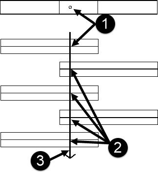
Top view
(upper) and side view (lower): 1) drilling hole, 2) these profiles are drilled
as well, 3) imaginary beam
Tip: You
can also adopt a drill hole field with simultaneous bolted connections into a
new shape so the new shape is drilled first and then bolted. To do this first
open the shape properties (),
and select the
 edit tool (magnifying glass) in
the
tab. The Drill dialog opens where you can adopt the drill holes with bolts,
select
 ( Add parts to a
bolting) in Bolts tab.
|
| Preview
|
Dynamically displays the design of the drill hole
field and the insertion point prior to applying it to a shape.
|