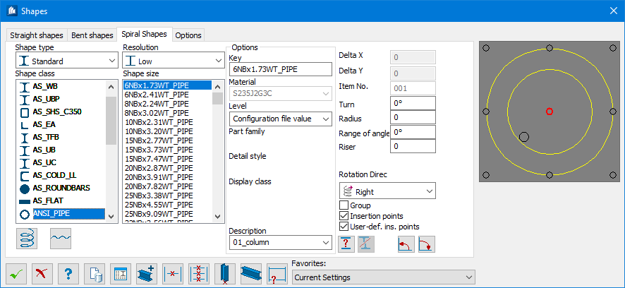
| Shape Type
|
Select the general shape type here. The
ProStructures shapes are divided into the
following different types:
- Standard –
These are shapes based on a data base included in the standard delivery range.
- User – These
are shape definitions which you can create yourself by drawing the
cross-section once and creating a shape out of this cross-section.
- Roof/Wall
Panel – These are special shapes created by you which have been
optimized for roof-wall installation.
- Combined
Shape – These are shapes which are combined out of several already
defined types.
- Weld
Shapes – These are also user-defined and permit any shape which can
be welded by means of plates.
- SPC Standard – These
are hot rolled shapes included in Bentley Structural Property Catalog.
Note: To use
this option, you must have
Bentley Structural Property
Catalog installed on your computer and select a version of the
SPC Version to use from the
ProStructures Options dialog Shapes
tab. When you select a catalog version, you must restart
ProStructures in order to use
that catalog.
Limitations:
- Only SPC hot
rolled shapes with an equivalent geometric class in
ProStructures are supported
- Widget tables
are supported by
ProStructures locally
- Connection
tables in existing
ProStructures shape MDB files
are supported by
ProStructures locally
- If SPC is
missing locally, then the Shape Class and Shape Size fields will be blank in
the Shape Properties dialog Shape Type tab. This is similar behavior to when an
existing shape MDB file is missing on a system.
|
| Shape Class
|
Depending on the selected shape type, the available
shape catalogs are listed here. You can specify which catalogs for standard
shapes are listed by means of the Shape Catalog selection. For all other shape
types, the created shape catalogs are listed from the corresponding directories
on the hard drive.
|
| Resolution
|
Here, you select the resolution of the depiction
Low,
Normal and
High for special shapes to make the monitor
display clearer in case of complex types. You can change the resolution at any
time afterwards if a more detailed depiction is required for instance.
|
| Shape size
|
After a shape catalog is selected, all included
shape sizes are displayed in this list.
|
| Options
|
- Key - Each
shape has its own clear access key. This access key can be entered directly
here to create non-standardized shape sizes of tubes, flat steel, round iron,
etc.
- Material -
Selects the material of the shape.
-
Level - Specifies on which
level the shapes are created.
- Part
Family - If a family classes are defined, you can set them here.
The selection of the family class can influence the color of the part.
- Detail
Style - If detailing styles are defined, you can set them here.
- Display
Class - If display classes are defined, you can set them here.
- Area
Class - If area classes are defined, you can set them here.
- Description -
If general parts descriptions are defined, you can set them here. The selection
of the description can influence the color and the layer.
|
| Delta X
|
The insertion offset in x-direction; this field can
only be entered, if you have selected the position ‘Free’ as insertion point
(this is the biggest displayed insertion point).
|
| Delta Y
|
The insertion offset in y-direction; this field can
only be entered, if you have selected the position ‘Free’ as insertion point
(this is the biggest displayed insertion point).
|
| Item No.
|
An item number can be used directly here.
|
| Turn
|
Sets the angle of rotation used to turn the shape
around the insertion axis.
|
| Turn
|
Specifies the shape's rotation angle in degrees.
|
| Radius
|
Sets the range of the spiral shape applied to its
insertion point.
|
| Range of
|
Sets the angle range for the spiral in degrees.
|
| Riser
|
Sets the elevation height for a 360° turn of the
spiral.
|
| Rotation
|
Selects either a
Right or
Left direction of rotation.
|
| Group
|
When on, creates a group out of the shape after
insertion.
|
| Insertion points
|
When on, the standard insertion points of the shape
are displayed.
|
| User-def. ins. points
|
When on, the user-defined insertion points of the
shape are displayed.
|
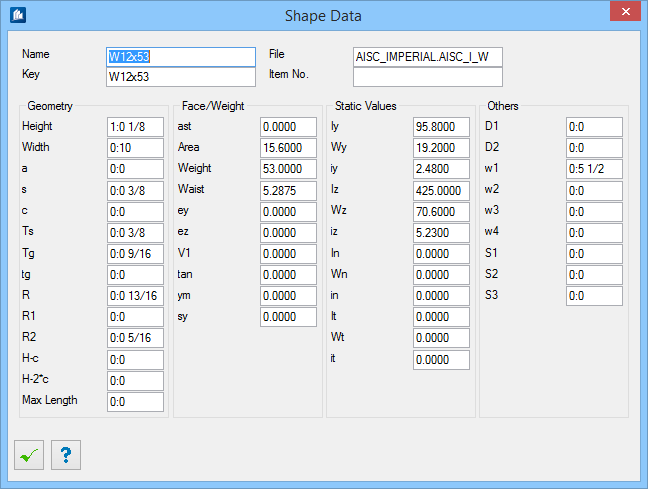
 Shape Data Shape Data
|
Opens the Shape Data dialog, which displays the
parameters for the selected shape.
|
 Interrupt dialog Interrupt dialog
|
Typically, inserted shapes are tentative (connected
with the dialog), so subsequent modifications can be transferred to inserted
shapes. If you do not want this functionality, you can interrupt the
connection using
. However, the shape is not
deleted.
|
 Rotate positive Rotate positive
|
The shapes are rotated in a positive direction
(turned left in shape direction) around their insertion point using the entered
value.
|
 Rotate negative Rotate negative
|
The shapes are rotated in a negative direction
(turned right in shape direction) around their insertion point using the
entered value
|
| Preview
|
Displays the selected shape as a cross-section.
Insertion points are shown as well. Select one of these points to insert the
shape at this insertion axis in longitudinal direction. Additional to the
corner and center points, more points appear with a slightly smaller depiction
(hole crack, center of gravity or manually created insertion points at special
shapes) as well as a larger points (free placing).
|
 Create by
dialog data Create by
dialog data
|
Click to create a spiral shape using the spiral parameters in
this dialog.
|
 Along planar
spline Along planar
spline
|
Used to create a spiral shape along a planar spline entity. Click
this tool to identify a spline element.
|