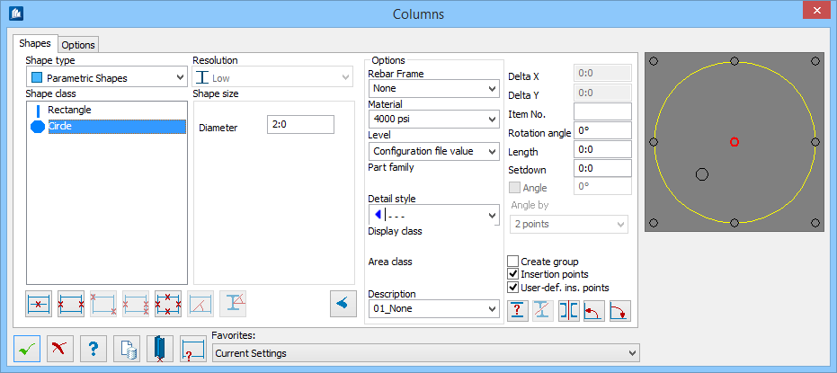
| Shape type
|
Sets the shape catalog that contains your
user-defined shape from the list.
|
| Shape class
|
Sets the shape class from the list of those
available for the selected Shape type.
|
| Resolution
|
Sets the detail resolution used from the list.
|
| Shape size
|
Type the parametric dimensions or select the
user-defined shape name.
- Width – Width
dimension of rectangular beams and columns.
- Depth – Height
dimension of rectangular beams and columns.
- Diameter –
Diameter of
circular beams and columns.
|
| Options
|
- Rebar
Frame(s)
– Sets Rebar view frame for concrete, selected
from the list.
- Material – Sets
a predefined material from the list.
- Level – Select
the CAD
level on which the
beam will be placed.
- Part
Family – If you model contains any named part families, they will
be listed there. Select one to add the new column to this part family.
- Detail
Style – If detailing styles are defined, you can set them here by
selecting from the list.
- Display
Class – If your model contains any named display classes, they will
be listed there. Select one to add the new column to this display class.
- Area
Class – If you model contains any named area classes, they will be
listed there. Select one to add the new column to this area class.
- Description –
Sets an object description from the list. The selection of the description can
influence the color and the layer.
|
| Delta X / Y
|
Location of the insertion point on the X / Y axis.
These fields are enabled when the biggest circle inside the cross-section of
preview is selected as insertion point. The insertion offset in x-direction;
this field can only be entered, if you have selected the position ‘Free’ as
insertion point (this is the biggest displayed insertion point).
|
| Item No.
|
An item number can be used directly here.
|
| Rotation
|
Places beams or columns at a specified angle.
|
| Length
|
Length dimension for beams and columns. Length is
only required if you are placing the beam by a single point. Otherwise, length
is automatically calculated based on work frame or line dimensions.
|
| Setdown
|
Distance from the concrete edge; allows the
reinforcing bars to extend past the edge of the beam.
|
| Angle
|
Enabled for non-zero length. When checked, enables
setting angle value. The field sets the angle to insert a shape.
|
| Angle by
|
Sets the method for specifying the angle from the
list; by Line or by two points. Enabled when
Angle is unchecked.
|
| Create Group
|
When checked, creates group of current shape
automatically at insertion of the beam.
|
| Insertion points
|
When checked, calculated insertion points of a shape
can be selected. Specifies the Insertion point for aligning the beam using the
graphical selection tool in the preview on the right side of the dialog. The black
circles indicate the available insertion points and the red
circle indicates the one which will be used.
Note: The color
scheme in the preview is determined by the settings for the
Monitor Colors in the
 ProStructures
Options ProStructures
Options dialog.
|
| User def. ins. points
|
When checked, user defined insertion points of a
shape can be selected.
|
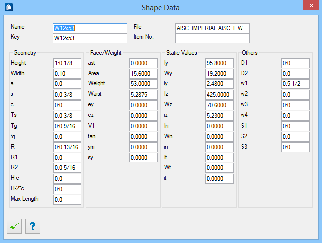
 Shape Data Shape Data
|
Opens the Shape Data dialog, which displays the
parameters for the selected shape.
|
 Interrupt dialog Interrupt dialog
|
Typically, inserted shapes are tentative (connected
with the dialog), so subsequent modifications can be transferred to inserted
shapes. If you do not want this functionality, you can interrupt the
connection using
. However, the shape is not
deleted.
|
 Mirror Mirror
|
All inserted shapes, which are still tentative
(connected with the dialog), are mirrored along their Y-axis. This is done by
exchanging the insertion points.
|
 Rotate positive Rotate positive
|
The shapes are rotated in a positive direction
(turned left in shape direction) around their insertion point using the entered
value.
|
 Rotate negative Rotate negative
|
The shapes are rotated in a negative direction
(turned right in shape direction) around their insertion point using the
entered value
|
| Preview
|
Displays the selected shape as a cross-section.
Insertion points are shown as well. Select one of these points to insert the
shape at this insertion axis in longitudinal direction. Additional to the
corner and center points, more points appear with a slightly smaller depiction
(hole crack, center of gravity or manually created insertion points at special
shapes) as well as a larger points (free placing).
|
 Insert on line Insert on line
|
First you are prompted to select a line. The end
points of this line are used as insertion points of the shape.
If it is unclear which of the line points is the
starting point and which is the end point,
ProStructures displays a cone for
asymmetrical shapes. The cone permits exchanging the insertion points and
allows you to obtain a shape mirrored about the y-axis.
If the selected line is a multi segmented line, a cranked
shape is inserted along the multi segmented line. Bend radii used for angled
shapes are specified on the Options tab
Radius setting. If set to 0, a minimum
radius is used.
|
 Insert two points Insert two points
|
First you are prompted to pick any two points in the
space, which then are used to insert the shape.
|
 Insert diagonally Insert diagonally
|
Available if an insertion point other than the middle
axis insertion points is selected as insertion point.
First you are prompted to select a line or to
select two points using the
"Point" option. The shape
is inserted along these points as follows: The selected insertion position at
the starting point is kept (e.g. center of the lower edge). At the end point,
however, the opposite position is used (in this case center upper edge).
If
Select Position after Insertion is
activated, the positions are exchanged with rotations by clicking the left
mouse button.
|
 Insert three points Insert three points
|
You first select the starting and end point where the
shape has to be inserted, then the third point defining the alignment. Dynamic
mode (see options) is activated automatically. The shape dynamically follows
each move of the mouse pointer so the position can be determined precisely.
|
 Insert on multiple lines Insert on multiple lines
|
Allows for the simultaneous insertion of several
shapes. Lines are selected simultaneously, and the desired shapes are inserted
along them.
If the lines are positioned in a way such that the
end points are coincident, the inserted shapes are mitred (if
is set to
0) or additional arcs with the
corresponding
Radius are inserted.
Tip: Depending on the selected insertion point, results can be
inconsistent. It is recommended to insert along the center line.
|
 Insert with angle and length Insert with angle and length
|
Enabled if you have indicated a fixed shape
Length. You are prompted for an insertion
point and for an alignment. Depending on the selection of the insertion point,
the shape is inserted along the alignment.
|
 Insert as cross section and
length Insert as cross section and
length
|
Enabled if you have indicated a fixed shape
Length. You are prompted for an insertion
point and for an alignment. The shape is inserted on the current XY-plane of
the UCS with the corresponding length to the back (into the depth).
|