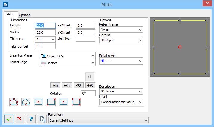
| Length
|
Sets the Length of the slab, for rectangular plate.
|
| Width
|
Sets the Width of the slab, for rectangular plate.
|
| Thickness
|
Sets Slab thickness, by entering the thickness or
selecting from the drop-down list.
|
| Height Offset
|
Sets the distance from the insertion point to the
bottom of the slab above selected insert ACS. Use an offset to raise (positive)
or lower (negative) the slab relative to the floor level.
|
| X-Offset / Y Offset
|
Sets slab offsets in X and Y directions.
|
| Item No.
|
Changes slab article number.
|
| Insertion Plane
|
Sets the drawing plane in which to insert the slab.
Selected from one of the options: Current UCS,
Object UCS, or User Defined Plane.
|
| Insertion Edge
|
Sets the insertion edge by which to place the slab:
Selected from one of the options: Bottom, Top, or
Middle.
|
 Accept Plate Accept Plate
|
Accepts current shape to prevent further changes.
When clicked, enables the below rotation options,
if the slab was inserted by line:
- -Phi – Rotates
the slab for the negative default value.
- +Phi – Rotates
the slab for the positive default value.
- -90 – Rotates
the slab by -90°.
- +90 – Rotates
the slab by -90°.
Rotation – Sets the rotation angle.
|
 Insert Polygon by Points Insert Polygon by Points
|
Define the shape of the slab by clicking existing
points on your model.
|
 Insert by Selected Polygon,
Circle, or Arc Insert by Selected Polygon,
Circle, or Arc
|
Define the shape of the slab by selecting an already
drawn Smartline in your model.
|
 Insert Rectangular Slab by
Insertion Point Insert Rectangular Slab by
Insertion Point
|
Place a rectangular shaped slab on your model using
dimensions set up in the tool's dialog box.
|
 Insert Rectangular Slab by
Selected Diagonal Insert Rectangular Slab by
Selected Diagonal
|
Define a slab by picking two existing parallel lines
from within your model.
|
 Insert Rectangular Slab Along a
Line Insert Rectangular Slab Along a
Line
|
Place a rectangular slab along an existing line.
|
 Insert Rectangular Slab by Four
Points Insert Rectangular Slab by Four
Points
|
Define the slab by selecting four existing points
from your model.
|
| Options
|
- Rebar
Frame(s)
– Sets Rebar view frame for concrete, selected
from the list.
- Material – Sets
a predefined material from the list.
- Level – Select
the CAD
level on which the
beam will be placed.
- Part
Family – If you model contains any named part families, they will
be listed there. Select one to add the new column to this part family.
- Detail
Style – If detailing styles are defined, you can set them here by
selecting from the list.
- Display
Class – If your model contains any named display classes, they will
be listed there. Select one to add the new column to this display class.
- Area
Class – If you model contains any named area classes, they will be
listed there. Select one to add the new column to this area class.
- Description –
Sets an object description from the list. The selection of the description can
influence the color and the layer.
|
| Level
|
Sets the slab level selected from the level list.
|