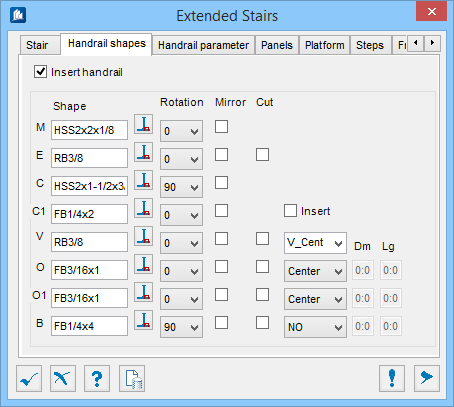
| Insert handrail
|
When checked, places handrails along the entire
stair using the shapes selected. The following settings determine how the
handrails come in and what they look like.
Note: Platforms may
not have handrails appear at the end if no closing shape has been enabled (see
Insert Handrail in Platform tab).
|
| Shape
|
The currently specified shape for the respective
component.
 (Select Shape tool) – Opens the
Shape Selection dialog, used to select a catalog shape from a list of standard
shapes and sizes. (Select Shape tool) – Opens the
Shape Selection dialog, used to select a catalog shape from a list of standard
shapes and sizes.
The illustration in the preview in the right will change to
show which piece is being defined as you go through each of the shapes.
- M – Displays
the defined shape for the main post.
- E – Displays
the defined shape for the main post extension. If
Cut is set, the shape will be cut.
- C – Displays
the defined shape for the top handrail.
- C1 – Displays
the defined shape for the terminating vertical shape.
- Insert – When
checked, creates the Closure shape component. Meaning, the final post of the
handrail on the platform end will use the terminating vertical shape (C1) shape
instead of the main post (M) shape. Also the terminating vertical shape (C1)
shape will extend down along the outside end of the platform stringer.
- V – Displays
the defined shape for the filling rods.
- V-Position
Shape (dropdown) – Determines how the vertical filling rods (V) are
placed; not at all, vertically -inside, -centered, -outside, and horizontally
-inside, -centered, -outside, all combinations are available here.
- O – Displays
the defined shape for the top rail. This goes near the top of the post and is
typically the termination point for the top of the filling rods.
- O-Position
Shape (dropdown) – Determines how the top rail (O) is placed; not
at all, inside, centered, outside and crossing, all combinations are available
here.
- O1 – Displays
the defined shape for the bottom rail. This goes near the bottom of the post
and is typically above the kick plate and the termination point for the bottom
of the filling rods.
- O1-Position
Shape (dropdown) – Determines how the bottom rail (O1) and
determines how it is placed; not at all, inside, centered, outside and
crossing, all combinations are available here.
- B – Displays
the defined shape for the kick plate.
- O1-Position
Shape (dropdown) – Determines how the kick plate (B) is placed; not
at all, inside, centered, outside and crossing, all combinations are available
here.
Dm and
Lg – Selecting the
Crossing Position Shape for
O,
O1, and
B the angular orientation of the crossing
option allows defining a slotted hole using these values for intersecting
members. Each of the other settings will cut at the intersection of the members
in question.
- Dm – If
Crossing is selected as the
Position Shape, type in the
Diameter of the respective hole for each
crossing rail.
- Lg – If
Crossing is selected as the
Position Shape, type in the
Slot Length of the respective hole for
each crossing rail.
|
| Rotation
|
All of the rotation icons work in conjunction with
the shape specified on their left (M, E, C, C1, V, O, O1, B). The desired
rotation of the selected shape can be defined here. Select a rotation angle (at
90° increments) from the drop-down list.
|
| Mirror
|
When checked, the shape orientation is mirrored along
its longitudinal axis. Here you can mirror the shape specified on their left
(M, E, C, C1, V, O, O1, B) if needed.
|
| Cut
|
When checked, cuts the shapes defined to the left
so that they will be flush against any intersecting members. An example of this
would be the filling rods (V) if enabled would be cut flush
with the top rail (C) .
|