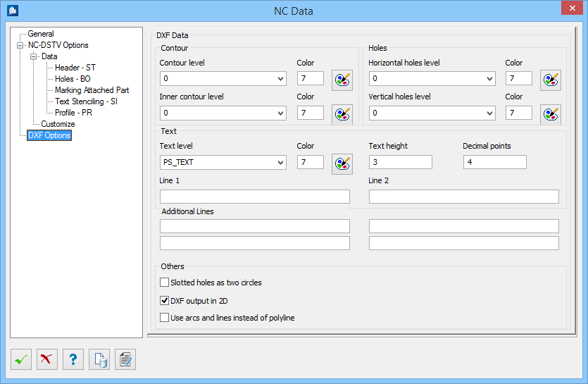
| Contour level and Color
|
Name of the outer contour level and color number of
the level.
Default values: Level =
0, Color =
7
Note: You may use
the
 to pick a color in Color
selection dialog.
|
| Inner contour level and Color
|
Name of the inner contour level and color number of
the level.
Default values: Level =
0, Color =
7
|
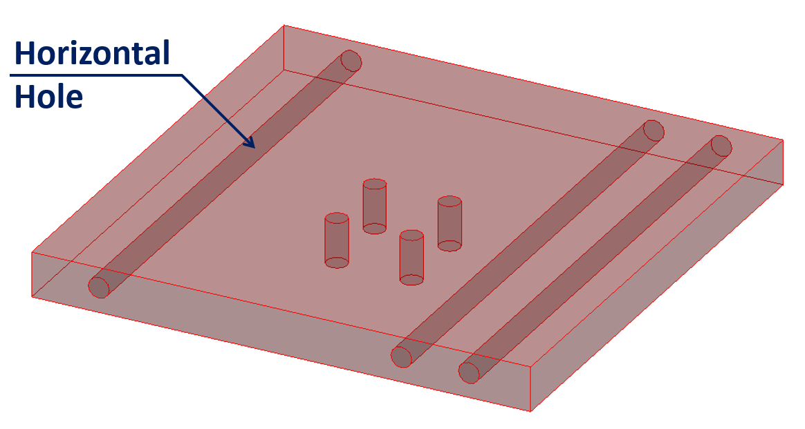
| Horizontal Hole level and Color
|
Name of the horizontal holes level and color number.
Note: Horizontal
holes are perpendicular to the thickness of a plate are used in straight plates
only.
Default values: Level =
0, Color =
7
|
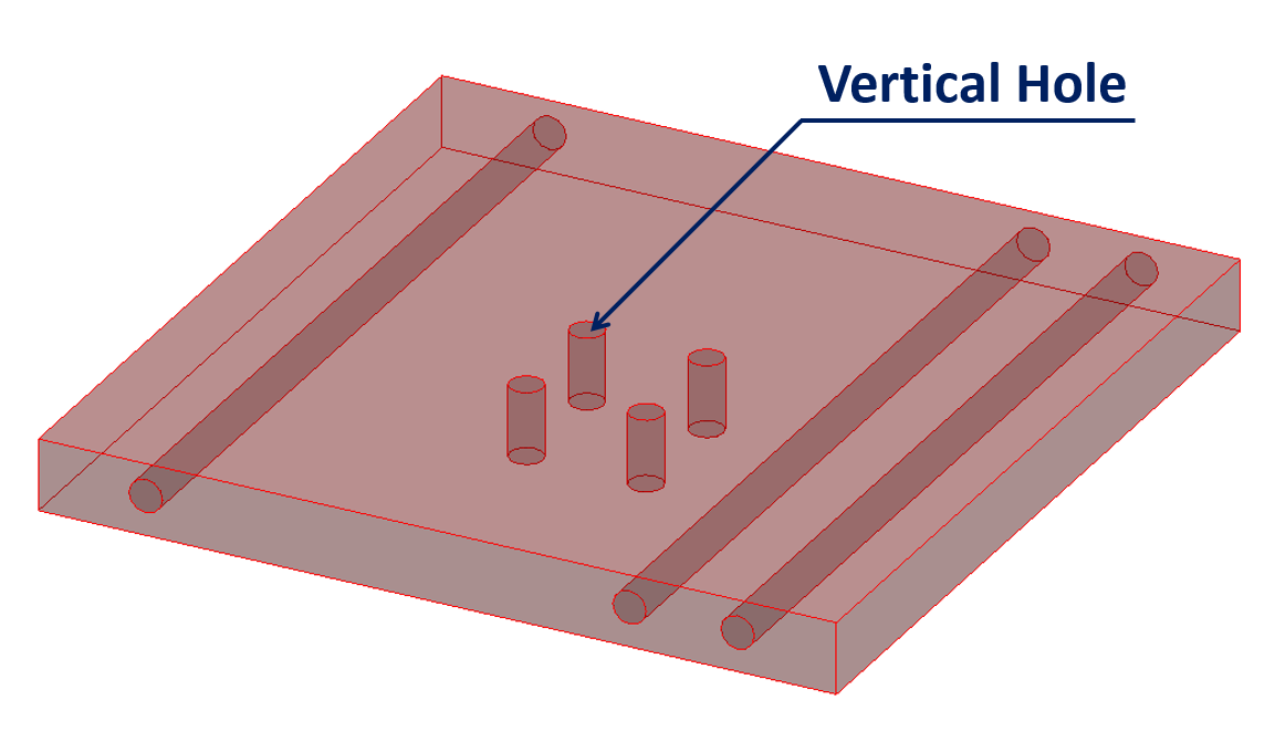
| Vertical Hole level and Color
|
Name of the vertical hole level and color number.
Default values: Level =
0, Color =
7
|
| Text level and Color
|
Name of the text level and color number.
Default values: Level =
PS_TEXT, Color =
7.
|
| Text Height
|
Sets the Height of the output text of line1 and
line2
Default value:
1/8" (Imperial units),
3mm (Metric units).
|
| Decimal Points
|
Defines the number of exported digits after the
decimal point of the DXF output. This influences the accuracy of the exported
DXF files.
Default value:
4.
|
| Line1/2
|
Any additional text which is written into the output
file (Bottom corner on the left of output, and above
Additional Lines); wildcards may be used.
The list of wildcards is as follows:
%DAY%file creation date
%MONTH%file creation date
%YEAR%file creation date
%HOUR%file creation time
%MINUTE%file creation time
%DWG_PROJECT_NAME%Project name
%DWG_ORDER_NAME%Order name
%DWG_PROJECT_NUMBER%Project number
%DWG_ORDER_NUMBER%Order number
%DWG_DRAWING_NAME%Drawing name
%DWG_DRAWING_NUMBER%Drawing number
%DWG_DRAWING_INDEX%Drawing index
%DWG_CREATED_NAME%Created by
%DWG_CREATED_DATE%Created on
%DWG_CHECKED_NAME%Checked by
%DWG_CHECKED_DATE%Checked on
%DWG_CLEARED_NAME%Cleared by
%DWG_ CLEARED _DATE%Cleared on
%DWG_LVPOS1%LV Pos1
%DWG_LVPOS2% LV Pos2
%DWG_LVPOS3% LV Pos3
%DWG_LVPOS4% LV Pos4
%DWG_COMMENT1%Comment1
%DWG_COMMENT2% Comment2
%DWG_COMMENT3% Comment3
%DWG_COMMENT4% Comment4
%DWG_CUSTOMER%Customer
%DWG_DRAWING_PAGE%Drawing page
If the part belongs to a group
%GROUPNAME%Group name
%GROUPNOTE1%Comment 1
%GROUPNOTE2%Comment 2
%GROUPPOSNUM%Position number
%GROUPSENDNUM%Shipping number
%GROUPARTICLE%Article number
%GROUPCOUNT%Number of groups %GROUPTOTALCOUNT%Overall number
%GROUPFAMILYCLASS%Family class %GROUPWEIGHT%Group weight
%GROUPLENGTH%complete group length
%GROUPWIDTH%complete group width
%GROUPHEIGHT%complete group height
For all other objects (if available)
%NAME%Name
%TRANSPORTNAMETransport name
%INTERNALNAME%Internal Name
%KEY%Shape key
%NOTE1%Comment1
%NOTE2%Comment2
%KATALOG%Catalogue
%POSNUM%Position number
%SENDNUM%Shipping number
%ORIGINALNUM%Original Position number
%ARTICEL%Article number
%HANDLE%
			 AutoCAD®
		   Handle
%STYLENAME%Name of detailing style
%MATERIAL%Material number
%COUNT%Quantity
%TOTALCOUNT%Total quantity
%PARTART%Part Type
%DISPLAYCLASS%Display class as number
%AREACLASS% Area class as number
%FAMILYCLASS% Family class as number
%PPSZPART%Marker for PPS output
%AREACLASSNAME%Area class
%DISPLAYCLASSNAME%Display class
%FAMILYCLASSNAME%Family class
%SHAPECLASS%Shape class
%COLORINDEX%Object colour
%FREEDESCRIPTION%Additional description
%LENGTH%Length
%WIDE%Width
%HEIGTH%Height
%SLOPEDHEIGTH%Sloped height
%WEIGHT%Weight
%CUTAREA%Cut area
%PAINTAREA%Paint area
%LENADD%Additional length
%INSERTX%Insert offset X
%INSERTY%Insert offset Y
%SCALE%Scaling factor
%TENSION%Tension (bolt)
%DM%Diameter (bolt)
%KLEMMLEN%Clamp length (bolt)
%MOUNTINGBOLT%Bolt type
%ORIGIN%Point of insertion
%XAXIS%X-axis
%YAXIS%Y-axis
%ZAXIS%Z-axis
%GROUPREL%Group relevation
%MODIFYFLAG%Modify flag
|
| Additional Lines
|
Used for further need of writing additional text
into the output file, as above.
|
| Slotted Hole as Two Circles
|
Ehen checked, a slotted hole is exported with two
holes. A slotted hole display in DXF as two circles —two arcs with two lines,
instead of with one hole.
|
| DXF Output as 2D
|
When checked, exports the exported geometry as
plane contour, in 2D. All z-coordinates of the geometry are reset to 0 at
output.
|
| Use arcs and lines of instead of Smartlines
|
Enabled for
DXF Output as 2D. Uses Arcs and Lines
instead of Smartline, serves for division of Smartlines into arcs and lines at
output.
|