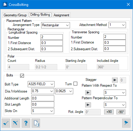
| Arrange Type
|
Set the layout type for the hole fields;
- Rectangular –
enables settings for rectangular type layout.
- Polar – enables
settings for radial type layout.
The drilling pattern will be applied according to
the members forming the pairs and it will not be possible to have the pattern
according to the supporting member. The entered pattern will be repeated on
every pair.
|
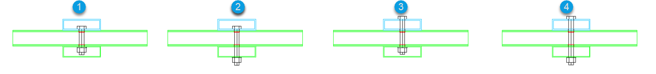
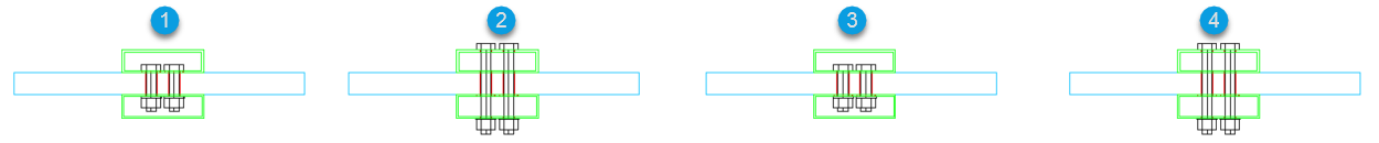
| Drill Type
|
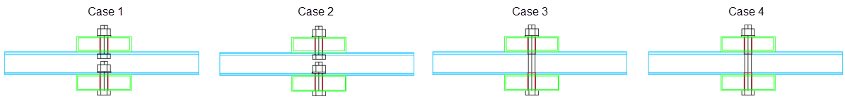
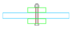
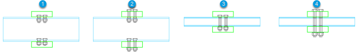
Sets one of the four drilling cases, that determines
which flange to other flange the shape be drilled and bolted.
All the shapes in the below Figure are hollow and
the support members are indicated in blue and located between the connecting
members.
Hollow
support in center
- Case
1 – The bolts go from the top flange of
the supporting member to the bottom flange of the top connecting member and
from the bottom flange of the supporting member to the top flange of the bottom
connecting member.
- Case
2 – The bolts go from the top flange of
the supporting member to the top flange of the top connecting member and from
the bottom flange of the supporting member to the bottom flange of the bottom
connecting member.
- Case
3 – The bolts go from the bottom flange
of the top connecting member to the top flange of the bottom connecting member.
- Case
4 – The bolts go from the top flange of
the top connecting member to the bottom flange of the bottom connecting member.
|
| Longitudinal Spacing
|
Enabled for Rectangular type layout pattern.
- Number – Sets
the number of bolts to be placed on the longitudinal direction. It's the X
orientation for the polyplate member, and Z orientation for shape member
according to which the pattern is set.
- First
Distance – Sets the distance from the starting edge to the center
of the first bolt.
- Subsequent
Distance – Sets the subsequent distance between longitudinal bolts.
Note: Distances
can be entered as direct values or as multiples of the bolt diameter. To enter
a multiplier of a bolt diameter as a distance, an *
precedes the multiplier of the bolt diameter. If a bolt has a diameter of 1
inch, then entering a distance of
*2 will result in a
2 inch distance.
|
| Transverse Spacing
|
Enabled for Rectangular type layout pattern.
- Number – Sets
the number of bolts to be placed on the transversal direction. It's the Y
orientation for the polyplate member, and the other direction for shape member
according to which the pattern is set.
- First
Distance – Sets the distance from the starting edge to the center
of the first bolt.
- Subsequent
Distance – Sets the subsequent distance between transversal bolts.
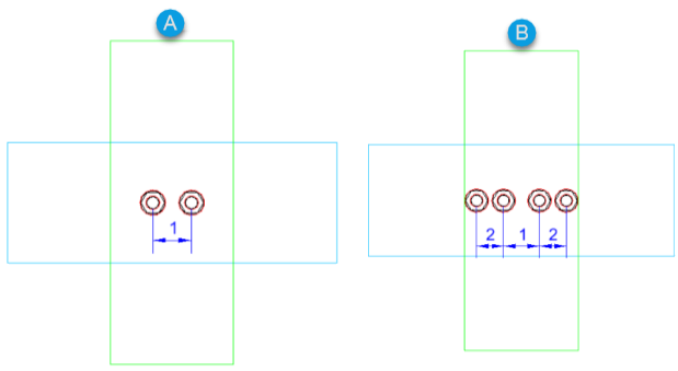
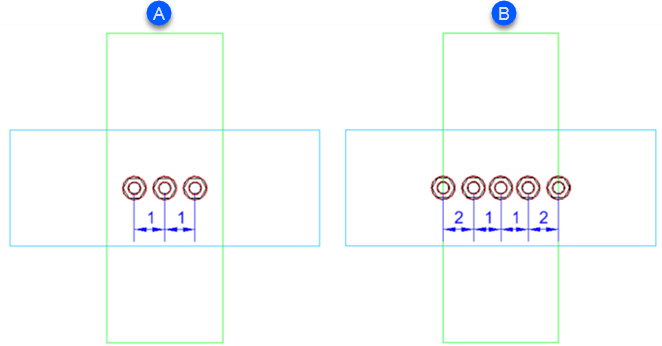
Examples: If the number of bolts in a
direction is
even, the user enters a first distance
between the bolts (1) and a subsequent distance between the bolts (2). If there
are only two bolts in a direction, the subsequent distance (2) is ignored. See
Figure 1 and Figure 2.
|
| Polar (radial)
|
Enabled for Polar type layout pattern.
- Count – Sets
the number of holes in the radial hole field.
- Radius – Sets
the radius of the radial pattern.
- Starting
Angle – Defines the starting angle of the distribution of the
radial hole field in relation to the insert axis.
- Included
Angle – Indicates the angle for which the radial holes will be
distributed, ranges between 0° and 360°.
Note: The radial
drilling pattern is not available in paired mode
|
| Bolts
|
- Bolt
Type – Sets the bolt style from the drop-down list.
- Diameter – Sets
the hole diameter of the selected bolt from the drop-down list of bolt diameter
table.
- Workloose –
Sets the clearance between bolt and hole diameter.
- Additional
Length – Sets an additional length to the bolts extension outside
the nut.
- Slot
Length – Sets the slotted hole distance along longitudinal
direction.
- Slots
On – Indicates the member or pair on which slots will be applied.
- Turn – When
checked, the bolt direction is inverted. Available when not welded.
Stagger - Click to increment
the stagger bolts stages (0-4). Applicable to pair mode selection.
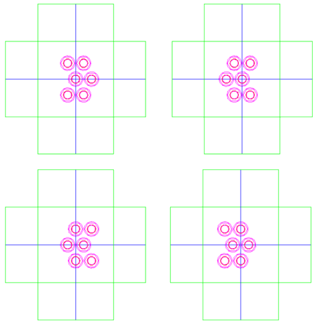
Staggered Bolting
When using a rectangular drilling pattern only, it
is possible to have staggered bolts. There are 4 cases of staggered bolting.
Bolts can be staggered in the longitudinal direction of the supporting shapes.
Staggered bolts are also supported for polyplates. The bolts will be staggered
in the X direction of the polyplate.
- The top 2 images have their
odd numbered rows of bolts
staggered and the bottom 2 images have their
even numbered rows of bolts
staggered.
- In the 2 images to the left, the bolts are
staggered to the
right and in the 2 images to the
right the bolts are staggered to the
left.
The bolts are staggered by half the first distance
between the bolts if there are only 2 or 3 bolts in the longitudinal direction
for member mode or 1 bolt in the longitudinal direction for paired mode. If
there are more than 3 bolts in the longitudinal direction for member mode or
more than 1 bolt for paired mode (the number of bolts is repeated on the other
side), they are staggered by half the subsequent distance between bolts.
|
| Pattern with respect to
|
Indicates the member according to which the pattern
is applied. In case of paired mode, the pattern is according to the members
forming the pair. Use the
> icon to travel through valid pattern
members in the list.
|
| Pattern perpendicular to
|
Indicates the member according to whose surface the
drilling is perpendicular to. In case of paired mode, the pair to whoich a
member belongs is indicated. Use the
> icon to travel through valid
perpendicular to members in the list.
|
| Rotation Angle
|
Sets the axial rotation of the bolt.
You can decide which member will have slots applied
to it. The orientation of the slots can only turn by 90°. When in paired mode,
if a shape forming a pair has slots applied to it, the other shape will also
have slots applied to it. Slot orientation and alignment is according to the
member defining the drilling/bolting pattern.
+90º turns the slots by 90º
counterclockwise, and
-90º turns it by 90º clockwise.
|