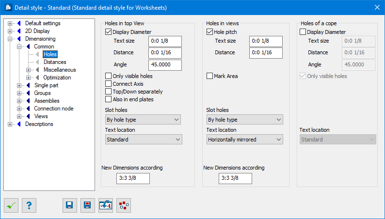
| Holes in Top View
|
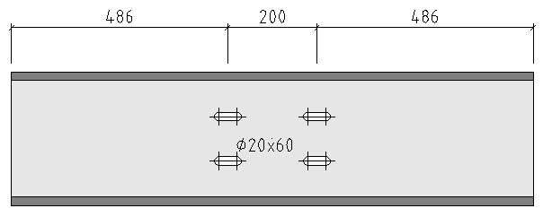
Settings for hole in top view, the hole diameter is
written beside the hole groups.
|
| Display Diameter
|
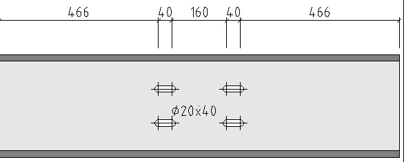
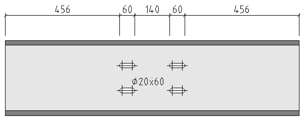
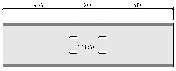
When checked, the diameter is only indicated once per
hole row or complete hole group, when the value doesn’t change. The text is
always aligned in main dimensioning direction.
- Text
Size – Enter the text size for labeling here.
- Distance –
Here, you can indicate the distance of the insertion point of diameter labeling
from the hole. This distance is measured from the border of the hole.
- Angle – Here
you can enter the angle between the insertion point of diameter labeling and
the hole, between -180° and +180°. The value 0 corresponds to the main
dimensioning direction. You can indicate positive (rotating to the left) and
negative values.
|
| Only Visible Holes
|
Only those holes are dimensioned which are visible
in the corresponding view. At a plan view for example, the holes of the shape’s
bottom flange are not dimensioned unless they were visible due to gaps in the
upper flange.
|
| Connect Axes
|
Common axis lines are displayed within the hole
groups if the ‘Divide Hole Groups’ setting has been checked.
|
| Divide Top/Bottom
|
The drill holes of upper and bottom side of the
component part are dimensioned in an individual dimension chain. The
assignment refers to the relative position towards view plane (Z=0).
|
| Also in end plates
|
The hole diameter is also given for folded plate
details.
|
| Slot Holes
|
Here you can select how to dimension and label
oblong holes. You may choose between different combinations of hole axes and
hole lengths to dimension according to production.
For more detailed information please refer to the
general explanations with regard to oblong holes.
|
| Text Location
|
Sets the location of the text; Standard, Mirrored
—Vertically, Horizontally, or Symmetrically.
|
| New Dimensions..
|
Here, you enter the distance from one hole group
resp. drill hole dimensioning to the other at which a new (redundant)
dimensioning has to be carried out. This permits a clearer dimensioning of far
away positioned identical hole screen dimensions as the dimension chains resp.
the indications of diameters are repeated.
|
| Holes in Views
|
Settings for continuous constant back pitches
displayed as a group.
|
| Hole Pitch
|
When checked, You enter the back pitches including
the diameter of the parallel drill holes.
|
| Text Size
|
Here, you enter the text size for back pitch labeling.
|
| Distance
|
Here, you can indicate the distance of back pitch
labeling from the edge of the component part. Positive values signify a
labeling outside the component part, negative values signify a labeling inside
the component part.
|
| Mark Area
|
Beginning and end of a hole group are displayed by a
marking.
|
| Slot Holes
|
Here you can select how to dimension and label
oblong holes. You may choose between different combinations of hole axes and
hole lengths to dimension according to production.
For more detailed information please refer to the
general explanations with regard to oblong holes
|
| Text Location
|
Sets the location of the text; Standard, Mirrored
—Horizontally.
|
| New Dimensions according
|
Here, you enter the distance from one back pitch to
the other at which a new (redundant) dimensioning has to be carried out. This
permits a clearer dimensioning of far away positioned identical back pitches as
the indications are repeated.
|
| Holes of a cope
|
Settings for diameter of cope holes.
|
| Display Diameter
|
The hole diameter is written beside the hole groups.
If the value doesn’t change, the diameter is only indicated once per hole row
or complete hole group. The text is always aligned in main dimensioning
direction.
- Text
Size – Enter the text size for labeling here.
- Distance
– Here, you can indicate the distance of the
insertion point of diameter labeling from the hole. This distance is measured
from the border of the hole.
- Angle – Here
you can enter the angle between the insertion point of diameter labeling and
the hole, between -180° and +180°. The value 0 corresponds to the main
dimensioning direction. You can indicate positive (rotating to the left) and
negative values.
|
| Only Visible Holes
|
Only those holes are dimensioned which are visible
in the corresponding view. At a plan view for example, the holes of the shape’s
bottom flange are not dimensioned unless they were visible due to gaps in the
upper flange.
|
| Text Location
|
Sets the location of the text; Standard, Mirrored
—Vertically, Horizontally, or Symmetrically.
|