| General
|
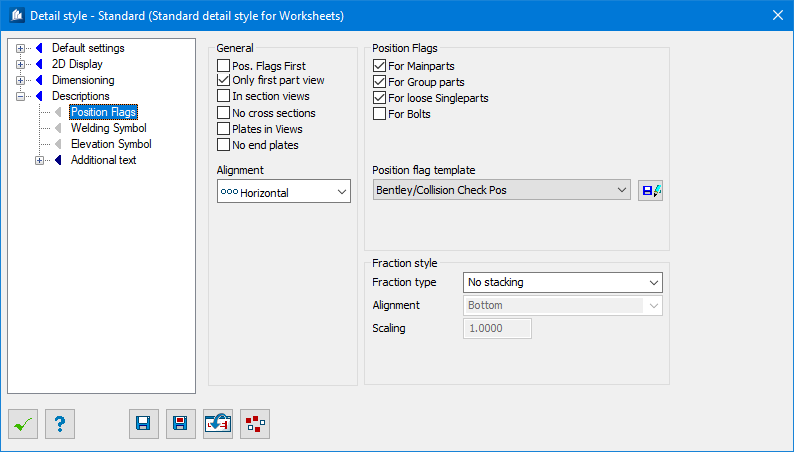
Sets position flags placement options.
|
| Pos. Flags First
|
The position flags are attached before part
dimensioning so that they are near the part.
|
| Only First Part View
|
In case of several partial views of a detail, the
position flags are only attached to the first view (except for possible 2D cuts
and folded end plates).
|
| In Section views
|
Position flags are also attached to all 2D-cuts.
|
| No cross sections
|
Position flags are not attached to component parts,
which are visible as cross-sections in the view.
|
| Plates in Views
|
A position flag is also attached to poly-plates and
stiffeners in model-views (overviews).
|
| Alignment
|
Here, you select the alignment of the position flags
in the detail drawing.
- Horizontal –
all position flags are aligned horizontally.
- Vertical – all
position flags are aligned vertically.
- Style Settings
– all position flags are aligned as indicated in the distribution style.
|
| Position Flags
|
Sets position flags grouping options.
|
| For Main Parts
|
A position flag is attached to the main parts of
construction groups.
|
| For Group Parts
|
A position flag is attached to the sub-parts of
construction groups.
|
| For Loose Single Parts
|
A position flag is attached to the component parts
not belonging to a group.
|
| For Bolts
|
A position flag is attached to the bolts of a
construction group.
|
| Pos. Flag Template
|
Here, you select the template for automatic
distribution of position flags. The template controls what has to be displayed
in the individual position flags, how the flag is structured and according to
which criteria the distribution in the detail or in the view is effected.
You create a distribution template in the
positioning command and only load it here.
|
 Create Distribution
template Create Distribution
template
|
Click on this button to move directly to the dialog
tab for setting the distribution templates. You can modify the selected
template or create new ones.
Note: You have to
save a modified template first before the modifications become valid.
|
| Fraction Style
|
Provides settings to control the appearance of each
annotation element in a 2D drawing.
|
| Fraction Type
|
Sets the type of a stacked fraction. If an annotation
text is related to a dimension style (e.g. hole diameter), the fraction
settings are used from that style. Here you can set either horizontal, diagonal
stacking or no stacking.
- No
Stacking – used as default when an old drawing is loaded. There are
no stacked fractions visible until that style will be changed (requires an
element update) or some new elements will be created.
- Horizontal
Stacking – Aligns the stacked fraction horizontal. (e.g. 0
1–4').
- Diagonal
Stacking – When set, stacks the fractions diagonally. (e.g. 0¼').
Text display resulting from element property data (e.g. shape
length, is shown as ‘10:6 3/8’) could be different regarding how this text have
been created. If it consists of basic
MicroStation text that is already part of the
DGN nothing will change. However, when a text is embedded into a
ProStructures element that is
calculated and drawn on runtime, this text display will change to a better
display style. It will happen when the element display is updated and includes
fraction stacking too.
|
| Alignment
|
Sets the alignment of the stacked fraction of
selected style annotation. The alignment influence how to the fraction display
be aligned.
- Bottom – Aligns
in the annotation element at bottom.
- Center – Aligns
in the annotation element in the center.
- Top – Aligns in
the annotation element at top.
|
| Scaling
|
Indicates the text size scaling of stacked fraction.
The scaling values are set to 1.0 (of text size) by default.
|