| Group selection tree
|
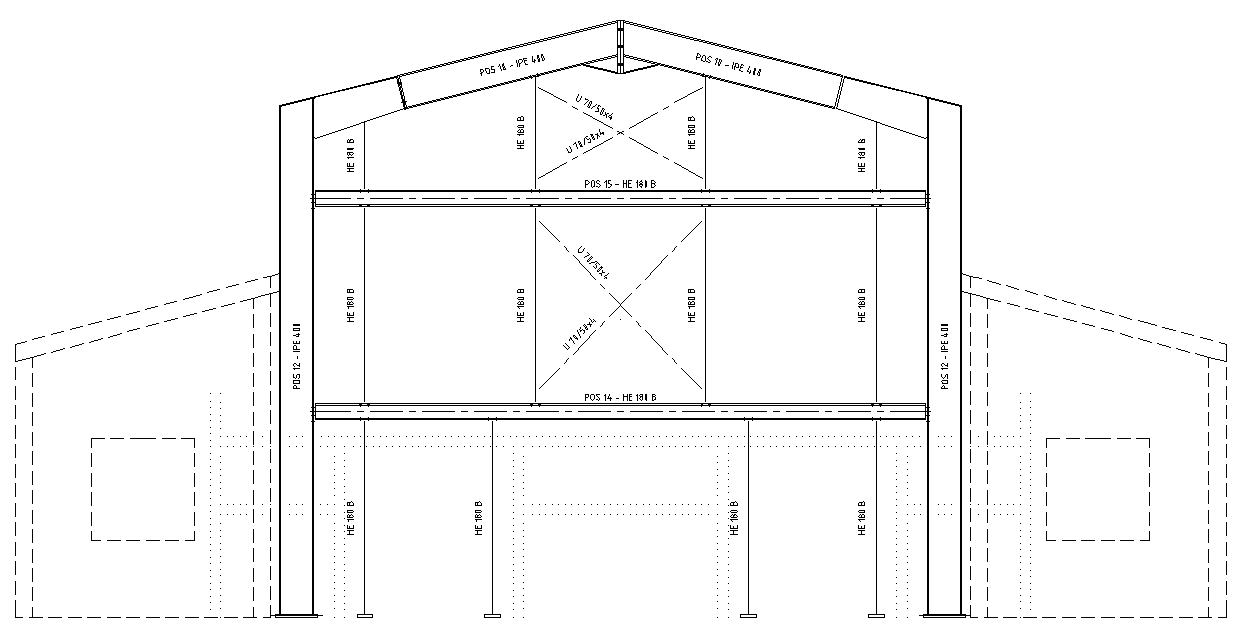
Here you select which parts will be represented in
the overview plans and how they are to be represented.
|

 Primary/secondary view Primary/secondary view
|
Here you select whether you wish to process the
settings for the primary or secondary view. You always process the settings
represented by the symbol currently displayed.
|
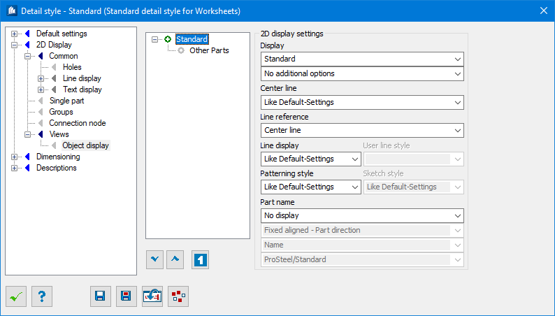
| 2D Display Settings
|
You define corresponding rules and attribute these
rules to the part types that you wish to include.
Note: Since the
procedure at this point is in principle very similar to the definition of
customized dimensioning rules (and is documented in detail there), much
information and many functions are to be found in the description of
"Dimensioning." The procedure is consequently explained very briefly below and
only the differences are described in detail.
|
| Display (1st field)
|
The basic form of representation of a part. Not
all parts can be represented in all versions that differ from the standard
version.
- No
display – The part is not represented.
- System
line – Parts are only represented as center lines (if possible).
- Single
Line – Parts are only represented as
single lines (if possible), whereby this can also be another reference line
alongside the middle line.
- Single
Line with Widget – The profiles are
only indicated as single line with widget representations. These lines with
widgets do not have to be visible from the beginning until the end of the part,
but can also be displayed as a center line.
- Outline –
Profiles are represented with the calculation of a simplified outer contour
without details.
- Standard – The
part is represented with the calculation of all available object edges.
- As
Object – The part is represented as a single, independent object
(’intelligent’ 2D component).
- Like
Primary – The part presentation follows that of
(primary view).
|
| Display (2nd field)
|
Here you can input further specifications regarding
the selected representation form if necessary.
- No
additional option – The part is represented without any further
changes according to the variant represented.
- No
holes – No holes are displayed.
- No hidden
lines – No hidden lines are displayed.
- No hidden
lines, holes – No hidden lines or holes are displayed.
- Equal
line colors – All lines are displayed in the color of the visible
lines.
- Equal
line colors and styles – All lines are displayed in the color and
with the line type of the visible lines.
- No
Reinforcement – No reinforcement objects for the component are
displayed
- No hidden
lines, no reinforcement – No covered lines and also no
reinforcement are displayed
- Symbols A
/ Symbols B – On selection of "Single Line" bracing and moment
connection elements are represented with special symbols. See "Symbolic
display."
- 2D mode /
3D mode / 2D symbol – Available for "As Object" Display. Sets one
of the display options to the object The part is shown in the 2D-Mode, 3-D
Mode, or simply a symbol in 2D.
|
| Center line
|
Independently of the general specifications, you
can activate and/or deactivate the display of center lines here.
- Like
default-settings – The center line is displayed in line with the
standard specifications for the center line of the detailing style.
- Do not
display
– The center line is never shown.
- Always
display – The center line is always displayed.
|
| Line reference
|
Here you select the starting and end point for the
display of the center / single line.
- Center
line – The center line displayed corresponds to the center line of
the part.
- Reference
line – The center line displayed corresponds to the reference line
of insertion line of the part.
- Reference
points – The center line displayed corresponds to the line between
both reference points of the part (if available).
|
| Line display
|
Here you select the combination of line type and
color (see also 2D-Display/General/Line display). The selection normally refers
to the visible lines.
- Like
default-settings – All lines are represented according to the
standard specifications for the line display of the detail style.
- Visible,
hidden etc.
– The visible lines (depending on the setting,
however, the hidden and center lines too) are represented with the line
representation selected.
- User#
– Line style is taken from user style. Activated
the User Line style settings.
- User
Line style – One of the user line styles is selected here.
|
| Patterning Style
|
Here you select whether or not o pattern the line in
standard specification.
- Without
patterning – No patterning is applied.
- Like
default-settings – All line patterns are represented according to
the standard specifications for the line display of the detail style.
|
| Sketch Style
|
Available for "Single Line" and "Single Line with
Widget" Display. Sets the sketch styles for display, e.g. Like
default-settings or one from other available sketch styles.
|
| Part Name (1st field)
|
The position of the additional label text on the
part.
- No
display – No labeling text is represented.
- Start of
Part – The text is represented above the part at the start of the
part.
- First
Section of Part – The text is represented above the part in the
front area.
- Part
Mid – The text is represented above the part in the middle.
- End of
Part – The text is represented above the part at the end of the
part.
- Next to
Part – The text is represented on the right side of the part.
- Inside
Part (Mid)
– The text is represented inside the part in the
middle.
- Inside
Part (First Section)
– The text is represented inside the part in the
front area.
- Downside
of Part – The text is represented below the part in the middle.
- Rotated
next to Part – The text is represented on the right side above the
part at a 45° angle.
|
| Part Name (2nd field)
|
Selection of the additional information that is to
be displayed in the label text.
- Name – The part
name is given.
- Short
Name – The short name of the part (from profile data base, if any)
is displayed. Otherwise the name is displayed.
- Position
Number – The position number is given.
- Shipping
Number – The shipping number is given.
- Name and
Elevation – The short name of the part and the relative position of
the component to the representation plane are indicated.
- Short
Name and Elevation – The part name and the relative position of the
part to the view plane are given. See also "Relative height reference."
- Global
format string (Detail Style) – The text is given according to the
format specification of the detail style (see description of "labeling"‘). This
specification may contain placeholders for the current part data.
- Individual format string
(Note2)
– The text is given according to the format
specification of the part (Entry "Note 2"). This specification can contain
placeholders for the current part.
- Individual or global format
string
– The text is given according to both format
specifications. If no entry is available in the part (individual specification)
the format specification of the detail style (global specification) is used.
Note: The 3 rd field of Part
Name is used to select the color for the user line type.
|