Combination Horizontal Brace
 Used to parametrically create
combination horizontal braces, which can be placed on any pipe or HSS tube as a
supporting shape, with equal or unequal leg angles as connecting shapes.
Used to parametrically create
combination horizontal braces, which can be placed on any pipe or HSS tube as a
supporting shape, with equal or unequal leg angles as connecting shapes.
Though combination horizontal brace connections are commonly used in electrical substation trestles, this tool can also be used for many other purposes.
Accessed from: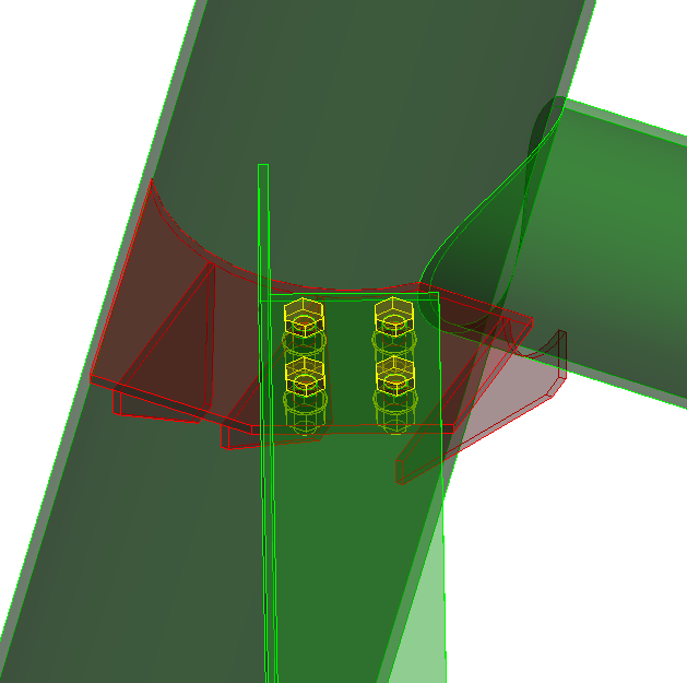
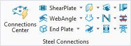
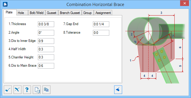
Plate tab
Used to specify geometry for the connecting gusset plate.
| Setting | Description |
|---|---|
| Thickness | Sets the thickness of the plate. Denoted with 1 in the diagram. |
| Angle | Controls the geometry of the plate where it is attached to the supporting trestle leg. Denoted with 2 in the diagram. |
| Dis to Inner Edge | Sets the width of the plate where it supports the horizontal tube brace. Denoted with 3 in the diagram. |
| Half Width | Sets the width of the plate on the outside of the horizontal angle brace. Denoted with 4 in the diagram. |
| Chamfer Height | Sets the height of the large plate chamfer where the horizontal angle brace is supported. Denoted with 5 in the diagram. |
| Dis to Main Brace | Sets the height of the plate where it supports the horizontal tube brace. Denoted with 6 in the diagram. |
| Gap End | Sets the gap between the end of the horizontal brace and the trestle leg. Denoted with 7 in the diagram. |
| Tolerance | Used to set a gap where the plate contacts the trestle leg. Denoted with 8 in the diagram. |
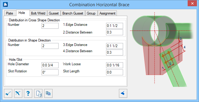
Hole tab
Used to specify bolt hole arrangement for bolted connections of braces to plate.
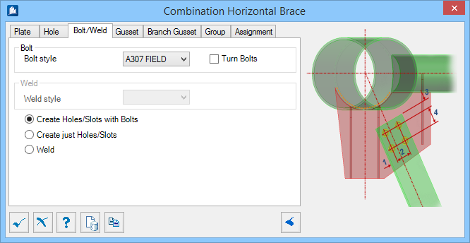
Bolt/Weld tab
Used to specify bolt and weld material data, as well as select the connection method used.
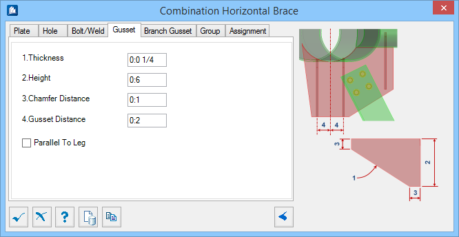
Gusset tab
Used to specify the geometry of the supporting pair of gusset plates.
| Setting | Description |
|---|---|
| Thickness | Sets the thickness of the plate. Denoted with 1 in the diagram. |
| Height | Sets the overall height of the Gusset. Denoted with 2 in the diagram. |
| Chamfer Distance | Sets the size of the chamfer corners. Denoted with 3 in the diagram. |
| Gusset Distance | Sets the gap between the two Gussets attached to the trestle main leg. Denoted with 4 in the diagram. |
| Parallel to Leg | When on, the gusset plates are oriented parallel to the connecting member. |
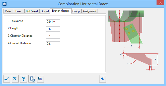
Branch Gusset tab
| Setting | Description |
|---|---|
| Thickness | Sets the thickness of the plate. Denoted with 1 in the diagram. |
| Height | Sets the overall height of the Branch Gusset. Denoted with 2 in the diagram. |
| Chamfer Distance | Sets the size of the chamfer corners. Denoted with 3 in the diagram. |
| Gusset Distance | Sets the gap between the Branch Gusset and the second Gusset. Denoted with 4 in the diagram. |
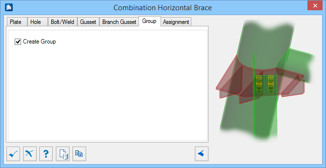
Group tab
Used to create a new ProStructures group with the Substation Gallery objects.
| Setting | Description |
|---|---|
| Create Group | Select this option to select additional shapes. Separate Substation Gallery objects are created. |
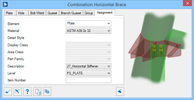
Assignment tab
Used to assign elements in the connection to a material, display class, area class, part family, level, etc.
Dialog Controls
| Setting | Description |
|---|---|
 OK OK
|
Closes the dialog and save your changes. |
 Cancel Cancel
|
Closes the dialog without saving changes. |
 Help Help
|
Opens online help. |
 Template Template
|
Saves and retrieve (Using Templates) settings to be used on other projects. |
 Clone Clone
|
Shifts focus to the geometry, allowing cloning the current structural object (stair, frame, truss, etc.) properties to match one or more objects selected in the view. |
  Show /Hide
Preview Show /Hide
Preview
|
Opens or closes, respectively, a flyout panel to display an illustration based on the tool. |