To Use the Select Tool in the 3D View
Follow these steps to use the Select Tool in the 3D view.
-
Click
Select Tool (
 ), and then click
Selection Tool Settings (
), and then click
Selection Tool Settings ( ).
).
A toolbar opens containing two sets of "Mode" options that you can use at any time to change the current selection set.
-
Click the
Mode option
 , and then click in the
model twice, drawing the endpoints of a line.
, and then click in the
model twice, drawing the endpoints of a line.
All objects intersected by this line become selected.
-
Click the
Mode option
 , and then click in the
model twice, drawing the endpoints of another line.
, and then click in the
model twice, drawing the endpoints of another line.
All objects intersected by this line become selected, and are added to the existing selection set.
-
Click the
Mode options
 and
and
 , and then click in the
model twice using a left-right direction, drawing the corners of a rectangular
range block.
, and then click in the
model twice using a left-right direction, drawing the corners of a rectangular
range block.
The existing selection set is replaced by a new one which consists of all objects inside the boundaries of the range block.
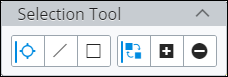
Whenever a selection set is made, an additional group of Select Tool icons appear in the 3D View. These allow you to manipulate the selection set.
-
Click
 Isolate Selected.
The display of all objects except the objects in the selection set is turned off.
The bottom of the 3D View has a toolbar with several tools that work with the Select Tool.
-
Click
 Clear Hide/Isolate/Emphasize.
The isolated view is cleared, and the view is redrawn. The un-displayed objects are again displayed.
-
Select
.
This will set the "Selection Scope" which affects how objects are selected based on their hierarchy in the digital twin.
-
Click the
Mode options
 and
, and click on an
object.
and
, and click on an
object.
The existing selection set is replaced by a new one which consists of all objects who are members of the top assembly the selected object is a member of.