Wire Sizing
This dialog helps you analyze an appropriate wire size for a selected device's connected power wiring.
The Wire/Core Sizing and Sustainability tool provides these key features on a per-picked-device basis:
- Size power wiring per electrical code standards (ex: National Electrical Code: NEC 2008 and NEC 2011).
- Account for de-rating factors such as fill, ambient temperature, wire type, voltage drop.
- Analyze sustainability (ex: power loss cost versus oversized wire cost; option for multiple smaller conductors per phase).
- Push selected wire size assignment out to selected wires for reporting.
- Output report summarizing the picked device's electrical requirements, its selected wire size, and optionally some sustainability estimates comparing wire costs versus annual energy loss costs in the wiring.
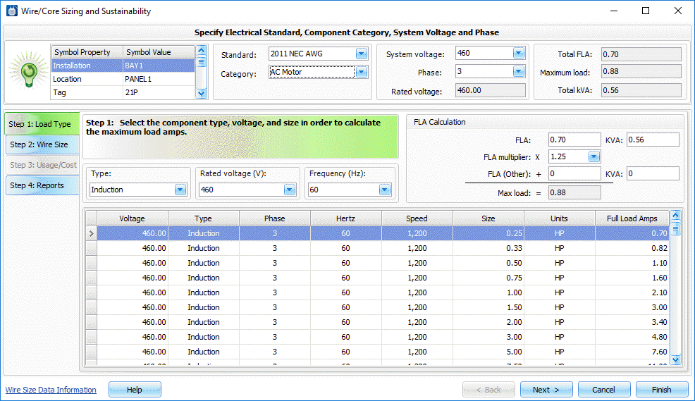
Step 1: Load Type
This tab identifies the selected device's load amp value (Full Load Amps : FLA). This value can then drive selection of an appropriate wire size in the subsequent tab. If additional information is provided such as system supply voltage and phase, then additional analysis related to voltage drop and power losses will be enabled on the Step 2 and 3 tabs.
| Setting | Description |
|---|---|
| Symbol Property/Value | Displays properties and values carried on the selected device. This is for display only! No direct editing is supported here. |
| Standard | The electrical code standard that the tool should follow regarding sizing of wires / cores. If the standard is set up to cover either AWG or Metric wire sizes, then there may be two standards selections available, one for each wire size standard (ex: 2011 NEC AWG; 2011 NEC METRIC). Note: use the companion wire sizing database editor utility to view/edit/add electrical code standard settings. |
| Category | Drives what category of data is displayed in the dialog's lower load size selection table. |
| System Voltage | Supply voltage value that is used in voltage drop calculation. It also affects what data is displayed in the dialog's lower load selection table. |
| Phase | Supply voltage phase (single or 3-phase) and is used to filter the data displayed in the dialog's lower load selection table. |
| Type | Type of load based upon Category selection above. Helps drives what data is displayed in the dialog's lower load selection table. |
| Rated Voltage (V) | Device rated voltage that, along with device FLA, is used to filter the load selection table display and is also used to calculate the device's kVA value |
| Frequency (Hz) | Electrical AC power frequency (ex: 50 or 60 Hz). This value is used to filter the load selection table display. |
| FLA | Device Full Load Amps" value. This is either filled from data held in the selected entry of the dialog's lower load selection table or is a manually typed-in value. |
| kVA | Device size measured in kilo-Volt-Amps. This value is tied to the FLA edit box value and the dialog's phase selection. Manually forcing a kVA value into this edit box will trigger a recalculation of the FLA value. |
| FLA Multiplier | Multiplier of FLA amp value for certain load types based upon electrical code requirements (ex: 1.25 for AC induction motors per the NEC). |
| FLA (Other) | Optional FLA value of other loads to be fed from a common set of power wiring can be manually entered into this edit box. |
| kVA (Other) | Optional kVA value of other loads to be fed from a common set of power wiring. This value is tied to the FLA (Other) edit box value and the dialog's phase selection. Manually forcing a kVA value into this edit box will trigger a recalculation of the FLA(Other) value. |
| Maximum Load | Maximum load amp rating, the sum of (FLA x FLA_Multiplier) + FLA(Other). |
| Total kVA | Sum of kVA + kVA(Other). |
| Load Selection Table | User's row pick from this table pushes the row's FLA value into the FLA edit box. This then drives the calculated Maximum Load value which, in turn, is key in selecting the minimum wire size in the Step 2 tab below. |
Manual FLA Entry
A FLA value can be manually typed into the FLA edit box and override any default FLA value held in the edit box that came from a selected row in the Load Selection Table. It will also trigger the kVA edit box value to recalculate. In like manner, any new row selection from the table will override the current FLA value held in this edit box (and the calculated kVA value), whether the original FLA value had been manually entered or not.
FLA Versus kVA Entry
The FLA and kVA edit box pairs are linked. Manually entering a value into one will update the other. Note: the conversion between FLA and kVA is affected by the row's Phase value selection.
System Voltage Versus Rated Voltage Entry
The system voltage value is used for voltage drop calculations : what percentage of the selected system voltage is lost in the power wiring as it makes its way to the connected load. The rated voltage is used for calculating the load's rated kVA value or effective impedance value based upon the load's rated FLA value. There is currently no validation that the selected system voltage is within range of a selected load's rated voltage. This is the responsibility of the user.
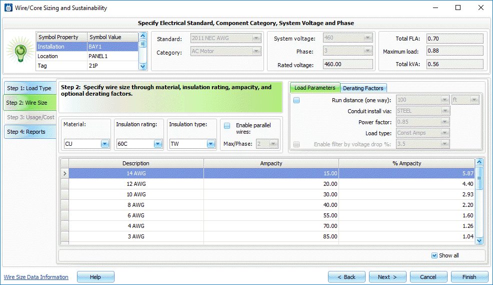
Step 2: Wire Size
This tab takes the Maximum load amps and the FLA values from the Step 1 tab and various settings and de-rating factors to determine the minimum wire size based upon the Step 1 tab's selected electrical code Standard.
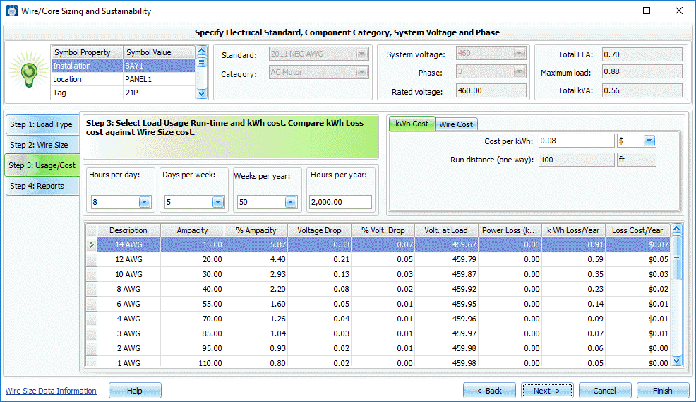
Step 3: Usage Cost
This tab takes effect only if Step 2 tab's Run Distance toggle is turned ON. Step 3 takes the selected wire size and wire/phase counts (if the Enable parallel wires options turned ON) and various settings and de-rating factors on Step 2 tab to determine the maximum annual electrical energy losses in the power wiring. This Step 3 tab display also lists other wire sizes meeting the load's ampacity requirements. This gives the user an option to select a larger, more efficient wire size or multi-wire combination. Cost comparisons are displayed in the right-hand column of the table in the bottom half of this Step 3 tab.
| Setting | Description |
|---|---|
| Usage Run-time Hours Per Year | User enters the annual hours that this set of wiring will feed the FLA value to the selected load device. This value used in the kWh energy loss calculation due to voltage drop in the power wiring. |
| Wire Cost | This estimate is for the power wires only and calculated for the defined one-way run distance. It does not include cost of conduit/raceway, ground/neutral wire(s), or installation / labor. Its purpose is to show the relative wire cost differential between a selected wire size and those wire sizes larger and smaller. The estimated one-time wire cost difference can be compared with the reoccurring kWh loss / year cost estimate to help guide in a sustainable design decision. |
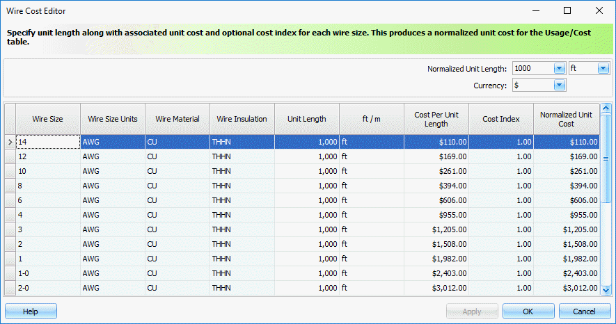
| Wire Cost Editor | Displays a sub-dialog showing the current cost assigned to each wire type. |
| Wire commodity index | This is a correction factor temporarily applied to the wire cost data. For example, if the current design is not expected to reach the procurement phase for another year and the projected cost of copper wire is expected to be 10% higher by then, a commodity index value of 1.1 will take this anticipated increase into account in the comparison calculations. |
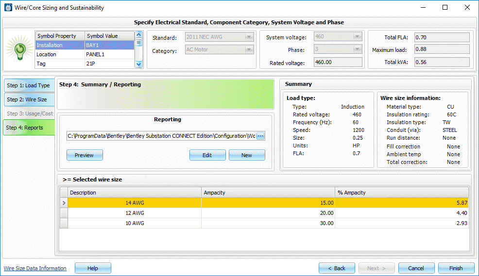
Step 4: Reports
This tab provides means to output a customized report that summarizes the load and the selected wire size. This report includes not only information on the selected wire size but also shows valid wire sizes that met the minimum requirements.
| Setting | Description |
|---|---|
| Report template selection | Browse to and select the desired .repx report template. |
| New | Creates a new report template. |
| Edit | Edit the selected report template. |
| Preview | Triggers report generation of the current load and wire size selection. |
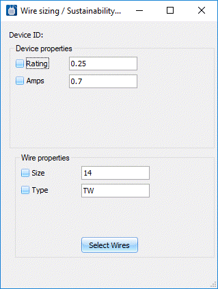
Wire Sizing/Sustainability Tool Dialog
This dialog displays after completing the wizard and enters you into an annotation mode.